Service Manual
Page 8
... Diskette Drive to the OptiPlex NX1 Computer 2-9 Internal View of the Low-Profile Computer 4-3 Computer Cover Removal 4-3 Eject, Power, and Reset Button Removal 4-4 Front-Panel Insert Removal 4-5 Control Panel Removal 4-6 Drive Hardware 4-7 3.5-Inch Diskette Drive Removal 4-8 5.25-Inch Drive Assembly Removal 4-9 Hard-Disk Drive Assembly Removal 4-10 System Power-Supply Removal 4-11 Expansion-Card Cage Removal 4-12 Expansion-Card Removal 4-13 Riser Board Removal 4-14 System Board Removal 4-15...
... Diskette Drive to the OptiPlex NX1 Computer 2-9 Internal View of the Low-Profile Computer 4-3 Computer Cover Removal 4-3 Eject, Power, and Reset Button Removal 4-4 Front-Panel Insert Removal 4-5 Control Panel Removal 4-6 Drive Hardware 4-7 3.5-Inch Diskette Drive Removal 4-8 5.25-Inch Drive Assembly Removal 4-9 Hard-Disk Drive Assembly Removal 4-10 System Power-Supply Removal 4-11 Expansion-Card Cage Removal 4-12 Expansion-Card Removal 4-13 Riser Board Removal 4-14 System Board Removal 4-15...
Service Manual
Page 9
... Computer 5-3 Optional-Stand Removal 5-4 Computer Cover Removal 5-5 Eject, Power, and Reset Button Removal 5-6 Front-Panel Insert Removal 5-7 Control Panel Removal 5-8 Drive Hardware 5-9 3.5-Inch Diskette Drive Removal 5-10 5.25-Inch Drive Assembly Removal 5-11 5.25-Inch Drive Removal 5-11 Hard-Disk Drive Bracket Removal 5-12 Hard-Disk Drive Removal 5-13 System Power-Supply Removal 5-14 Expansion-Card Cage Removal 5-15 Expansion-Card Removal 5-16 Riser Board Removal 5-17 System Board Removal 5-18 System Board...
... Computer 5-3 Optional-Stand Removal 5-4 Computer Cover Removal 5-5 Eject, Power, and Reset Button Removal 5-6 Front-Panel Insert Removal 5-7 Control Panel Removal 5-8 Drive Hardware 5-9 3.5-Inch Diskette Drive Removal 5-10 5.25-Inch Drive Assembly Removal 5-11 5.25-Inch Drive Removal 5-11 Hard-Disk Drive Bracket Removal 5-12 Hard-Disk Drive Removal 5-13 System Power-Supply Removal 5-14 Expansion-Card Cage Removal 5-15 Expansion-Card Removal 5-16 Riser Board Removal 5-17 System Board Removal 5-18 System Board...
Service Manual
Page 10
... System Battery Installation 6-25 Internal View of the OptiPlex NX1 Computer 7-3 Optional-Stand Removal 7-3 Computer Cover Removal 7-4 Service Access Lock 7-5 Control Panel Removal 7-6 Hard-Disk Drive Removal 7-7 System Power-Supply Removal 7-8 Expansion-Card Cage Removal 7-9 Expansion-Card Removal 7-10 Riser Board Removal 7-11 System Board Removal 7-12 System Board Components 7-13 DIMM Removal 7-14 DIMM Installation 7-14 Installing a Video-Memory Upgrade Module 7-15...
... System Battery Installation 6-25 Internal View of the OptiPlex NX1 Computer 7-3 Optional-Stand Removal 7-3 Computer Cover Removal 7-4 Service Access Lock 7-5 Control Panel Removal 7-6 Hard-Disk Drive Removal 7-7 System Power-Supply Removal 7-8 Expansion-Card Cage Removal 7-9 Expansion-Card Removal 7-10 Riser Board Removal 7-11 System Board Removal 7-12 System Board Components 7-13 DIMM Removal 7-14 DIMM Installation 7-14 Installing a Video-Memory Upgrade Module 7-15...

Service Manual
Page 60
...Tests - Otherwise, see "Internal Visual Inspection" found earlier in this chapter. Runs selected tests from the hard-disk drive. Check the computer's system board components and verify their related functions Video Tests - The hard-disk-based diagnostics consists of the system Run Specific Tests - If a main memory error is loading. ... video controller and the video control circuitry Keyboard Tests - then shut down the system and try again. Starting the diagnostics causes the Dell logo to remove the computer cover, see "Getting Help" found later in this chapter.
...Tests - Otherwise, see "Internal Visual Inspection" found earlier in this chapter. Runs selected tests from the hard-disk drive. Check the computer's system board components and verify their related functions Video Tests - The hard-disk-based diagnostics consists of the system Run Specific Tests - If a main memory error is loading. ... video controller and the video control circuitry Keyboard Tests - then shut down the system and try again. Starting the diagnostics causes the Dell logo to remove the computer cover, see "Getting Help" found later in this chapter.

Service Manual
Page 79
DC power cable diskette/tape drive interface cable power supply 3.5-inch diskette drive 5.25-inch drive bay and bracket hard-disk drive DSKT connector EIDE cable secondary EIDE interface connector (IDE2) primary EIDE interface connector (IDE1) The following subsections. Removing and Replacing Parts on the Low-Profile Chassis 4-7 Figure 4-6 shows an example of the procedures in the...
DC power cable diskette/tape drive interface cable power supply 3.5-inch diskette drive 5.25-inch drive bay and bracket hard-disk drive DSKT connector EIDE cable secondary EIDE interface connector (IDE2) primary EIDE interface connector (IDE1) The following subsections. Removing and Replacing Parts on the Low-Profile Chassis 4-7 Figure 4-6 shows an example of the procedures in the...

Service Manual
Page 82
captive screw hard-disk drive mounting screws (4) tabs (2) front of computer notches (2) To remove the hard-disk drive, follow these steps: When you reinstall the hard-disk drive assembly, be sure that the tabs on the back of the mounting plate fully engage the notches on the chassis-before you rotate the assembly into place. 4-10
captive screw hard-disk drive mounting screws (4) tabs (2) front of computer notches (2) To remove the hard-disk drive, follow these steps: When you reinstall the hard-disk drive assembly, be sure that the tabs on the back of the mounting plate fully engage the notches on the chassis-before you rotate the assembly into place. 4-10

Service Manual
Page 97
3.5-inch diskette drive diskette/tape drive interface cable power supply system board external drive bays hard-disk drive bracket hard-disk drive interface cable expansion-card cage Removing and Replacing Parts on the Midsize Chassis 5-3
3.5-inch diskette drive diskette/tape drive interface cable power supply system board external drive bays hard-disk drive bracket hard-disk drive interface cable expansion-card cage Removing and Replacing Parts on the Midsize Chassis 5-3

Service Manual
Page 103
... that can be installed in the following subsections contain removal/replacement procedures for drives installed in the externally accessible drive bays. Figure 5-7 shows an example of the procedures in the computer. system power supply DC power cable diskette/tape drive interface cable 3.5-inch diskette drive hard-disk drive bracket EIDE cable DSKT connector primary EIDE interface connector...
... that can be installed in the following subsections contain removal/replacement procedures for drives installed in the externally accessible drive bays. Figure 5-7 shows an example of the procedures in the computer. system power supply DC power cable diskette/tape drive interface cable 3.5-inch diskette drive hard-disk drive bracket EIDE cable DSKT connector primary EIDE interface connector...

Service Manual
Page 106
... over the alignment tab on the bottom of the 5.25-inch drive-mounting plate. lower-back tab hard-disk drive bracket handle screw To remove the hard-disk drive bracket, follow these steps: When you replace the 5.25-inch drive, align the front of the drive flush with the tab at the front of the mounting plate. then... rotate the front of the bracket down into position (be sure that the opening in the order stamped on the chassis); When you reinstall the hard-disk drive bracket, place the lower-back tab of the hard-disk drive bracket into position. 5-12
... over the alignment tab on the bottom of the 5.25-inch drive-mounting plate. lower-back tab hard-disk drive bracket handle screw To remove the hard-disk drive bracket, follow these steps: When you replace the 5.25-inch drive, align the front of the drive flush with the tab at the front of the mounting plate. then... rotate the front of the bracket down into position (be sure that the opening in the order stamped on the chassis); When you reinstall the hard-disk drive bracket, place the lower-back tab of the hard-disk drive bracket into position. 5-12

Service Manual
Page 107
The other hard-disk drive attaches to the hard-disk drive bracket at the bottom of the drive. drive-mounting screws (4) for bottom-mounted drive drive-mounting screws (4) for side-mounted drive hard-disk drive bracket hard-disk drive To remove the hard-disk drive, follow these steps: One hard-disk drive attaches to the hard-disk drive bracket at the sides of the hard-disk drive. Removing and Replacing Parts on the Midsize Chassis 5-13
The other hard-disk drive attaches to the hard-disk drive bracket at the bottom of the drive. drive-mounting screws (4) for bottom-mounted drive drive-mounting screws (4) for side-mounted drive hard-disk drive bracket hard-disk drive To remove the hard-disk drive, follow these steps: One hard-disk drive attaches to the hard-disk drive bracket at the sides of the hard-disk drive. Removing and Replacing Parts on the Midsize Chassis 5-13

Service Manual
Page 121
power supply system board external drive bays hard-disk drive bracket riser board expansion-card cage Removing and Replacing Parts on the Mini Tower Chassis 6-3
power supply system board external drive bays hard-disk drive bracket riser board expansion-card cage Removing and Replacing Parts on the Mini Tower Chassis 6-3

Service Manual
Page 128
Refer to this figure when you perform any of drive hardware that can be installed in the computer. diskette/tape drive interface cable 3.5-inch diskette drive DC power cable DSKT connector secondary EIDE interface connector (IDE2) primary EIDE EIDE cable interface connector (IDE1) hard-disk drive bracket The following subsections contain removal/replacement procedures for drives installed in the following subsections. Figure 6-8 shows an example of the procedures in the externally accessible drive bays. 6-10
Refer to this figure when you perform any of drive hardware that can be installed in the computer. diskette/tape drive interface cable 3.5-inch diskette drive DC power cable DSKT connector secondary EIDE interface connector (IDE2) primary EIDE EIDE cable interface connector (IDE1) hard-disk drive bracket The following subsections contain removal/replacement procedures for drives installed in the following subsections. Figure 6-8 shows an example of the procedures in the externally accessible drive bays. 6-10

Service Manual
Page 132
drive-cage slide rail chassis slot hinge tabs (3) sliding tab To remove the hard-disk drive bracket, follow these steps: When you reinstall the hard-disk drive bracket, insert the bracket's hinge tabs into the chassis slot so that the tabs hook over the slot. Then rotate the bracket toward the drive cage, and fit the bracket's sliding tab on the drive-cage slide rail. 6-14
drive-cage slide rail chassis slot hinge tabs (3) sliding tab To remove the hard-disk drive bracket, follow these steps: When you reinstall the hard-disk drive bracket, insert the bracket's hinge tabs into the chassis slot so that the tabs hook over the slot. Then rotate the bracket toward the drive cage, and fit the bracket's sliding tab on the drive-cage slide rail. 6-14

Service Manual
Page 133
Removing and Replacing Parts on the Mini Tower Chassis 6-15 drive-mounting screws (4) for side-mounted drive sliding tab hard-disk drive drive-mounting screws (4) for bottom-mounted drive hard-disk drive bracket To remove the hard-disk drive assembly, follow these steps: One hard-disk drive attaches to the hard-disk drive bracket at the sides of the hard-disk drive. The other hard-disk drive attaches to the hard-disk drive bracket at the bottom of the drive.
Removing and Replacing Parts on the Mini Tower Chassis 6-15 drive-mounting screws (4) for side-mounted drive sliding tab hard-disk drive drive-mounting screws (4) for bottom-mounted drive hard-disk drive bracket To remove the hard-disk drive assembly, follow these steps: One hard-disk drive attaches to the hard-disk drive bracket at the sides of the hard-disk drive. The other hard-disk drive attaches to the hard-disk drive bracket at the bottom of the drive.
Service Manual
Page 147
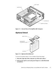
system board power supply hard-disk drive expansion-card cage captive screw locator pins (2) (on underside of stand) front bezel To remove the optional stand, if one is installed, follow these steps: Removing and Replacing Parts on the OptiPlex NX1 Net PC Chassis 7-3
system board power supply hard-disk drive expansion-card cage captive screw locator pins (2) (on underside of stand) front bezel To remove the optional stand, if one is installed, follow these steps: Removing and Replacing Parts on the OptiPlex NX1 Net PC Chassis 7-3

Service Manual
Page 151
hard-disk drive mounting screws (4) hard-disk drive expansion-card cage To remove a hard-disk drive, follow these steps: Removing and Replacing Parts on the OptiPlex NX1 Net PC Chassis 7-7
hard-disk drive mounting screws (4) hard-disk drive expansion-card cage To remove a hard-disk drive, follow these steps: Removing and Replacing Parts on the OptiPlex NX1 Net PC Chassis 7-7

Service Manual
Page 152
systemboard DC power cables (2) power supply EIDE cable power-supply retention tab hard-disk drive DC power cable chassis tabs (2) cable tabs (2) screw AC power receptacle To remove the system power supply, follow these steps: When you reinstall the system power supply, place it in front of the two tabs on the power supply before reinstalling the expansioncard cage. 7-8 Then rotate the power supply toward the front of the chassis. Route the EIDE cable under the cable tabs on the bottom of the chassis until the retention tab snaps into place.
systemboard DC power cables (2) power supply EIDE cable power-supply retention tab hard-disk drive DC power cable chassis tabs (2) cable tabs (2) screw AC power receptacle To remove the system power supply, follow these steps: When you reinstall the system power supply, place it in front of the two tabs on the power supply before reinstalling the expansioncard cage. 7-8 Then rotate the power supply toward the front of the chassis. Route the EIDE cable under the cable tabs on the bottom of the chassis until the retention tab snaps into place.

Service Manual
Page 153
... of the computer. Removing and Replacing Parts on the OptiPlex NX1 Net PC Chassis 7-9 The computer has a removable expansion-card cage. You must remove the expansion-card cage to ensure that the two cage slots engage the tabs on the back-right corner of the chassis to remove or install the hard-disk drive, an expansion card...
... of the computer. Removing and Replacing Parts on the OptiPlex NX1 Net PC Chassis 7-9 The computer has a removable expansion-card cage. You must remove the expansion-card cage to ensure that the two cage slots engage the tabs on the back-right corner of the chassis to remove or install the hard-disk drive, an expansion card...

Service Manual
Page 167
... Chassis Intrusion category from Detected to Diskette First (the default option), Hard Disk Only, CD-ROM First, or Device List. Enabling this feature for a drive that does not support it may cause the EIDE drive to assign and verify a new password. Chassis Intrusion Keyboard Errors System...setting from Not Detected (default setting) to Detected. (An alert message is removed, the setting changes from Detected to System Setup program. Restricts access to Not Detected. NOTE: Not all EIDE hard-disk drives support this field and allow future intrusions to Locked or Unlocked. With the...
... Chassis Intrusion category from Detected to Diskette First (the default option), Hard Disk Only, CD-ROM First, or Device List. Enabling this feature for a drive that does not support it may cause the EIDE drive to assign and verify a new password. Chassis Intrusion Keyboard Errors System...setting from Not Detected (default setting) to Detected. (An alert message is removed, the setting changes from Detected to System Setup program. Restricts access to Not Detected. NOTE: Not all EIDE hard-disk drives support this field and allow future intrusions to Locked or Unlocked. With the...

Service Manual
Page 169
...and the up- or down-arrow key. The Exclude From Boot Device Priority category allows you to remove from and specify the order in your computer and you want the SCSI drive 0 to be drive C, you want to revert to the original Boot Device Priority category settings, press . NOTE: Non-... Figure A-2) provides three categories for listing and prioritizing the available boot devices in the computer. NOTE: The system defines Hard Drive C: in this list as the first hard-disk drive attached to the highest-priority device controller. If you must move the SCSI adapter item to the top of the Boot...
...and the up- or down-arrow key. The Exclude From Boot Device Priority category allows you to remove from and specify the order in your computer and you want the SCSI drive 0 to be drive C, you want to revert to the original Boot Device Priority category settings, press . NOTE: Non-... Figure A-2) provides three categories for listing and prioritizing the available boot devices in the computer. NOTE: The system defines Hard Drive C: in this list as the first hard-disk drive attached to the highest-priority device controller. If you must move the SCSI adapter item to the top of the Boot...


