User Guide
Page 3
... on the system board may be faulty. The monitor's power indicator Most monitors have not resolved the problem, continue with video during POST indicate that an integrated system board device may be faulty or is incorrectly installed. l A solid yellow power ...green power indicator and no video during POST indicate that the monitor or the integrated video controller may be faulty. If the diskette-drive access indicator does not light up , see "Troubleshooting Drives." Remove all expansion cards, and then reboot. Otherwise, see "Dell Diagnostics." Table 1. In...
... on the system board may be faulty. The monitor's power indicator Most monitors have not resolved the problem, continue with video during POST indicate that an integrated system board device may be faulty or is incorrectly installed. l A solid yellow power ...green power indicator and no video during POST indicate that the monitor or the integrated video controller may be faulty. If the diskette-drive access indicator does not light up , see "Troubleshooting Drives." Remove all expansion cards, and then reboot. Otherwise, see "Dell Diagnostics." Table 1. In...
User Guide
Page 50
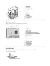
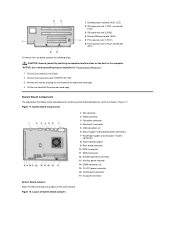
.... Figure 7. Figure 8. 1 External drive bay 2 Internal drive cage 3 Chassis intrusion switch 4 Hard-disk drive interface cable 5 Expansion-card cage 6 System board 7 Riser board 8 Padlock ring 9 Security cable slot 10 I/O ports and connectors 11 AC power receptacle 12 Power supply...Board Components Figure 7 shows the system board and the location of jumpers on the system board. System Board Jumpers System Board Components 1 NIC connector 2 Video connector 3 Fan connector 4 Serial port 2 connector 5 USB connectors (2) 6 Keyboard (lower) and mouse (upper) connectors 7 Parallel port (upper)...
.... Figure 7. Figure 8. 1 External drive bay 2 Internal drive cage 3 Chassis intrusion switch 4 Hard-disk drive interface cable 5 Expansion-card cage 6 System board 7 Riser board 8 Padlock ring 9 Security cable slot 10 I/O ports and connectors 11 AC power receptacle 12 Power supply...Board Components Figure 7 shows the system board and the location of jumpers on the system board. System Board Jumpers System Board Components 1 NIC connector 2 Video connector 3 Fan connector 4 Serial port 2 connector 5 USB connectors (2) 6 Keyboard (lower) and mouse (upper) connectors 7 Parallel port (upper)...
User Guide
Page 57
... computer cover, perform the following precautions. Back to Contents Page Internal Components: Dell™ OptiPlex™ GX100 System User's Guide Overview Troubleshooting Expansion Cards Safety First-For You and Your Computer Troubleshooting System Memory Removing and Replacing the Computer Cover Troubleshooting the Video Subsystem Troubleshooting a Wet Computer Troubleshooting a Damaged Computer Troubleshooting the System Board Troubleshooting...
... computer cover, perform the following precautions. Back to Contents Page Internal Components: Dell™ OptiPlex™ GX100 System User's Guide Overview Troubleshooting Expansion Cards Safety First-For You and Your Computer Troubleshooting System Memory Removing and Replacing the Computer Cover Troubleshooting the Video Subsystem Troubleshooting a Wet Computer Troubleshooting a Damaged Computer Troubleshooting the System Board Troubleshooting...

User Guide
Page 60
...printer or an external drive) gets wet, contact the manufacturer for at a slight angle as shown in the computer except a drive controller card and video expansion card. 5. b. Pivot the cover down toward the bottom of the chassis, insert the hooks on . Turn off the system, including any ...you remove the computer cover, see "Safety First-For You and Your Computer." 2. Also, disconnect any attached peripherals, and disconnect all expansion cards installed in Figure 6. 4. Face the left side of the cover to submerge your computer, spills, splashes, and excessive humidity can damage ...
...printer or an external drive) gets wet, contact the manufacturer for at a slight angle as shown in the computer except a drive controller card and video expansion card. 5. b. Pivot the cover down toward the bottom of the chassis, insert the hooks on . Turn off the system, including any ...you remove the computer cover, see "Safety First-For You and Your Computer." 2. Also, disconnect any attached peripherals, and disconnect all expansion cards installed in Figure 6. 4. Face the left side of the cover to submerge your computer, spills, splashes, and excessive humidity can damage ...
User Guide
Page 62
... an error message indicates an expansion-card problem or if an expansion card seems to perform incorrectly or not at all expansion cards except the video card. 6. If the tests complete successfully, repeat steps 8 and 9 with software or other hardware, or a faulty expansion card. Start the Dell Diagnostics by inserting the Dell ResourceCD and rebooting the system. 5. Troubleshooting...
... an error message indicates an expansion-card problem or if an expansion card seems to perform incorrectly or not at all expansion cards except the video card. 6. If the tests complete successfully, repeat steps 8 and 9 with software or other hardware, or a faulty expansion card. Start the Dell Diagnostics by inserting the Dell ResourceCD and rebooting the system. 5. Troubleshooting...
User Guide
Page 63
Check the monitor cable connections as indicated in "Troubleshooting Expansion Cards." If any of the tests fail, see "Getting Help" for instructions on obtaining technical assistance. Run the System Board Devices test group. If any of ... determine whether or not the monitor is the source of either the boot routine or the Dell Diagnostics, or if a drive is the source of the problem: the monitor, the monitor interface cable, or the integrated video subsystem. Run the appropriate test group for instructions on obtaining technical assistance. CAUTION: Before you...
Check the monitor cable connections as indicated in "Troubleshooting Expansion Cards." If any of the tests fail, see "Getting Help" for instructions on obtaining technical assistance. Run the System Board Devices test group. If any of ... determine whether or not the monitor is the source of either the boot routine or the Dell Diagnostics, or if a drive is the source of the problem: the monitor, the monitor interface cable, or the integrated video subsystem. Run the appropriate test group for instructions on obtaining technical assistance. CAUTION: Before you...
User Guide
Page 65
...up if your hard-disk drive has become unreliable. l Full compliance with Dynamic Video Memory (DVM) technology architecture. l Managed boot agent (MBA), which allows storage... management console. To use this capability, enable the USB support in NIC cards. Hardware Features Your system offers the following software is at speeds up to...Back to Contents Page Introduction: Dell™ OptiPlex™ GX100 System User's Guide Overview Hardware Features Software Features Manageability Features ENERGY STAR® Compliance Overview Dell OptiPlex GX100 Managed PC systems are running...
...up if your hard-disk drive has become unreliable. l Full compliance with Dynamic Video Memory (DVM) technology architecture. l Managed boot agent (MBA), which allows storage... management console. To use this capability, enable the USB support in NIC cards. Hardware Features Your system offers the following software is at speeds up to...Back to Contents Page Introduction: Dell™ OptiPlex™ GX100 System User's Guide Overview Hardware Features Software Features Manageability Features ENERGY STAR® Compliance Overview Dell OptiPlex GX100 Managed PC systems are running...
User Guide
Page 76
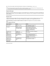
...." Record the message on obtaining technical assistance. Table 3. The monitor or the graphics card may result. These warning messages usually interrupt the procedure and require you run a test group or subtest in the Dell Diagnostics, an error message may be faulty. These particular error messages are generated by ...LED Code Blinking yellow Solid yellow Solid green and a beep code during POST Solid green power indicator and no beep code and no video during POST Solid green power indicator and no ). If the system does not boot, see "Getting Help" for instructions on obtaining ...
...." Record the message on obtaining technical assistance. Table 3. The monitor or the graphics card may result. These warning messages usually interrupt the procedure and require you run a test group or subtest in the Dell Diagnostics, an error message may be faulty. These particular error messages are generated by ...LED Code Blinking yellow Solid yellow Solid green and a beep code during POST Solid green power indicator and no beep code and no video during POST Solid green power indicator and no ). If the system does not boot, see "Getting Help" for instructions on obtaining ...
User Guide
Page 82
... reassign the serial port's designation if you have the Microsoft® Windows® 98, Windows 95, or Windows NT® 4.0 operating system, Dell already installed the necessary mouse drivers on " state.) l A dual-colored link integrity indicator, which your hardware, you install communications software. The mouse...up the serial ports and does not require an expansion card. The integrated parallel port uses a 25-pin D-subminiature connector on the back panel. The drivers also pass along the mouse data to your hard-disk drive. Video Connector The system uses a 15-pin high-density D-...
... reassign the serial port's designation if you have the Microsoft® Windows® 98, Windows 95, or Windows NT® 4.0 operating system, Dell already installed the necessary mouse drivers on " state.) l A dual-colored link integrity indicator, which your hardware, you install communications software. The mouse...up the serial ports and does not require an expansion card. The integrated parallel port uses a 25-pin D-subminiature connector on the back panel. The drivers also pass along the mouse data to your hard-disk drive. Video Connector The system uses a 15-pin high-density D-...
User Guide
Page 91
...serial ports at the same time. If you select On w/ MBA, you can set a serial port to Auto and add an expansion card containing a port configured to the same designation, the system automatically remaps the integrated port to the next available port designation that came with ... l Video DAC Snoop Press to configure these options to Auto (the default) to automatically configure a port, to 3BCh if you cannot use both at the Dell logo screen during system boot. Mouse Port Mouse Port enables or disables the system's integrated Personal System/2 (PS/2)-compatible mouse port. ...
...serial ports at the same time. If you select On w/ MBA, you can set a serial port to Auto and add an expansion card containing a port configured to the same designation, the system automatically remaps the integrated port to the next available port designation that came with ... l Video DAC Snoop Press to configure these options to Auto (the default) to automatically configure a port, to 3BCh if you cannot use both at the Dell logo screen during system boot. Mouse Port Mouse Port enables or disables the system's integrated Personal System/2 (PS/2)-compatible mouse port. ...

User Guide
Page 92
...controls the operation of the keys. With Read Only selected, nothing can be written to any diskette drives and tape drives using a video expansion card and problems such as necessary) is detected on your system boots with the Num Lock mode activated on the system board; PC ...is not installed. When Auto is selected, the system uses a video expansion card, if one is installed, or the onboard video controller if a video expansion card is On (the default) or Off. Video DAC Snoop Video DAC Snoop lets you correct video problems that may occur when you use when the system boots. If...
...controls the operation of the keys. With Read Only selected, nothing can be written to any diskette drives and tape drives using a video expansion card and problems such as necessary) is detected on your system boots with the Num Lock mode activated on the system board; PC ...is not installed. When Auto is selected, the system uses a video expansion card, if one is installed, or the onboard video controller if a video expansion card is On (the default) or Off. Video DAC Snoop Video DAC Snoop lets you correct video problems that may occur when you use when the system boots. If...
User Guide
Page 97
...UMB). For example, in the case of the network expansion card and expanded-memory page-frame address conflict, you can move the network card to the monitor may require a special screen driver program that expects a certain kind of video mode or monitor. In systems with your system can be... available for each installed expansion card. Because they remain in to log in the computer's memory, memory conflicts and errors can also cause...
...UMB). For example, in the case of the network expansion card and expanded-memory page-frame address conflict, you can move the network card to the monitor may require a special screen driver program that expects a certain kind of video mode or monitor. In systems with your system can be... available for each installed expansion card. Because they remain in to log in the computer's memory, memory conflicts and errors can also cause...
User Guide
Page 100
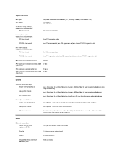
...card connector size ISA expansion-card connector data width (maximum) 98 pins 16 bits Drives Externally accessible bays: Small-form-factor chassis Low-profile chassis Mini tower chassis Internally accessible bays: Small-form-factor chassis Low-profile chassis Mini tower chassis Ports Externally accessible: Serial (data terminal equipment DTE) Parallel Video... bay for a 3.5-inch diskette drive; Expansion Bus Bus types Bus speed Small form-factor chassis expansion-card connectors: PCI riser board Peripheral Component Interconnect (PCI), Industry-Standard Architecture (ISA) PCI: 33 MHz ISA...
...card connector size ISA expansion-card connector data width (maximum) 98 pins 16 bits Drives Externally accessible bays: Small-form-factor chassis Low-profile chassis Mini tower chassis Internally accessible bays: Small-form-factor chassis Low-profile chassis Mini tower chassis Ports Externally accessible: Serial (data terminal equipment DTE) Parallel Video... bay for a 3.5-inch diskette drive; Expansion Bus Bus types Bus speed Small form-factor chassis expansion-card connectors: PCI riser board Peripheral Component Interconnect (PCI), Industry-Standard Architecture (ISA) PCI: 33 MHz ISA...
Service Manual
Page 11
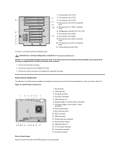
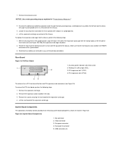
... on the system board. NOTICE: Use a wrist grounding strap as explained in the slots. 3. Remove the expansion cards installed in "Precautionary Measures." 1. System Board Components The subsections that follow contain procedures for removing system board components, which ...shared with ISA1) To remove the riser board, perform the following steps. Figure 18. Lift the riser board off the expansion-card cage. System Board Components 1 NIC connector 2 Video connector 3 Fan power connector 4 Serial port 2 connector 5 USB connectors (2) 6 Mouse (upper) and keyboard (lower) connectors...
... on the system board. NOTICE: Use a wrist grounding strap as explained in the slots. 3. Remove the expansion cards installed in "Precautionary Measures." 1. System Board Components The subsections that follow contain procedures for removing system board components, which ...shared with ISA1) To remove the riser board, perform the following steps. Figure 18. Lift the riser board off the expansion-card cage. System Board Components 1 NIC connector 2 Video connector 3 Fan power connector 4 Serial port 2 connector 5 USB connectors (2) 6 Mouse (upper) and keyboard (lower) connectors...
Service Manual
Page 12
... low-profile GX100 chassis can accommodate three 32-bit PCI expansion cards. NOTICE: Make sure your computer with a PSWD jumper installed, meaning that password features for connectors and sockets on a circuit board. Dell shipped your system is turned off its pin(s) and either ... DIMM socket Diskette/tape drive interface connector Integrated NIC connector Microprocessor fan connector EIDE interface connector Keyboard connector Microprocessor connector Video connector Mouse connector Control panel connector Parallel port connector; To change a jumper setting, pull the jumper off before ...
... low-profile GX100 chassis can accommodate three 32-bit PCI expansion cards. NOTICE: Make sure your computer with a PSWD jumper installed, meaning that password features for connectors and sockets on a circuit board. Dell shipped your system is turned off its pin(s) and either ... DIMM socket Diskette/tape drive interface connector Integrated NIC connector Microprocessor fan connector EIDE interface connector Keyboard connector Microprocessor connector Video connector Mouse connector Control panel connector Parallel port connector; To change a jumper setting, pull the jumper off before ...
Service Manual
Page 32
... strap as explained in the slots. 3. Remove the screws securing the riser board to the expansion-card cage. Remove the expansion cards installed in "Precautionary Measures." System Board Components The subsections that follow contain procedures for locating or removing... some of the computer. 1. Remove the expansion-card cage. 2. System Board Components 1 NIC connector 2 Video connector 3 Fan power connector 4 Serial port 2 connector 5 USB connectors (2) 6 Keyboard (upper) and mouse ...
... strap as explained in the slots. 3. Remove the screws securing the riser board to the expansion-card cage. Remove the expansion cards installed in "Precautionary Measures." System Board Components The subsections that follow contain procedures for locating or removing... some of the computer. 1. Remove the expansion-card cage. 2. System Board Components 1 NIC connector 2 Video connector 3 Fan power connector 4 Serial port 2 connector 5 USB connectors (2) 6 Keyboard (upper) and mouse ...
Service Manual
Page 33
...your system board and gives a brief description of their functions. Figure 25. Dell shipped your system or unpredictable results may occur. System Board Connectors and Sockets ...Integrated NIC connector Microprocessor fan connector EIDE interface connector Keyboard connector Microprocessor connector Video connector Mouse connector Control panel connector Parallel port connector; Table 1. System ... input connector Riser board connector Serial port connectors USB connectors Expansion Cards The mini tower GX100 chassis can accommodate up to your computer with a PSWD jumper installed...
...your system board and gives a brief description of their functions. Figure 25. Dell shipped your system or unpredictable results may occur. System Board Connectors and Sockets ...Integrated NIC connector Microprocessor fan connector EIDE interface connector Keyboard connector Microprocessor connector Video connector Mouse connector Control panel connector Parallel port connector; Table 1. System ... input connector Riser board connector Serial port connectors USB connectors Expansion Cards The mini tower GX100 chassis can accommodate up to your computer with a PSWD jumper installed...
Service Manual
Page 51
... the mating hooks on the system board. 3. To remove the PCI riser board, perform the following steps: 1. Remove the computer cover. Remove the expansion cards installed in "Precautionary Measures." 2. System Board Components 1 NIC connector 2 Video connector 3 Fan power connector 4 Serial port 2 connector 5 USB connectors (2) Reconnect any cables that has two PCI expansion...
... the mating hooks on the system board. 3. To remove the PCI riser board, perform the following steps: 1. Remove the computer cover. Remove the expansion cards installed in "Precautionary Measures." 2. System Board Components 1 NIC connector 2 Video connector 3 Fan power connector 4 Serial port 2 connector 5 USB connectors (2) Reconnect any cables that has two PCI expansion...
Service Manual
Page 53
...board connector Serial port connectors USB connectors Expansion Cards The small-form-factor GX100 chassis can accommodate up : ALERT! If necessary, disconnect any cables connected to Enabled or Enabled-Silent. To remove an expansion card, perform the following message to be displayed...PARALLEL POWER_1 POWER_2 RISER SERIALn USB Integrated NIC connector Microprocessor fan connector EIDE interface connector Keyboard connector Microprocessor connector Video connector Mouse connector Control panel connector Parallel port connector; Remove the screw on the chassis intrusion detector. Figure...
...board connector Serial port connectors USB connectors Expansion Cards The small-form-factor GX100 chassis can accommodate up : ALERT! If necessary, disconnect any cables connected to Enabled or Enabled-Silent. To remove an expansion card, perform the following message to be displayed...PARALLEL POWER_1 POWER_2 RISER SERIALn USB Integrated NIC connector Microprocessor fan connector EIDE interface connector Keyboard connector Microprocessor connector Video connector Mouse connector Control panel connector Parallel port connector; Remove the screw on the chassis intrusion detector. Figure...


