User Guide
Page 9
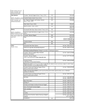
... Sales 525 U.S.A. (Austin, Texas) Customer Service 525 Main 525 Automated Order-Status System AutoTech (for portable and desktop computers) Dell Home and Small Business Group (for portable and desktop computers): Customer Technical Support (Return Material Authorization Numbers) Customer Technical Support (Home...): Customer Service and Technical Support (Return Material Authorization Numbers) toll free: 1-800-234-1490 Dell Sales toll free: 1-800-289-3355 toll free: 1-800-879-3355 Spare Parts Sales toll free: 1-800-357-3355 DellWare™ toll free: 1-800-753-7201 Desktop ...
... Sales 525 U.S.A. (Austin, Texas) Customer Service 525 Main 525 Automated Order-Status System AutoTech (for portable and desktop computers) Dell Home and Small Business Group (for portable and desktop computers): Customer Technical Support (Return Material Authorization Numbers) Customer Technical Support (Home...): Customer Service and Technical Support (Return Material Authorization Numbers) toll free: 1-800-234-1490 Dell Sales toll free: 1-800-289-3355 toll free: 1-800-879-3355 Spare Parts Sales toll free: 1-800-357-3355 DellWare™ toll free: 1-800-753-7201 Desktop ...
User Guide
Page 18
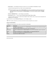
... of your printer connection in the Parallel Ports tests. Advanced Testing Help Menu The Help options and a description of their functions are part of your computer. NOTE: The options displayed on your screen should reflect the hardware configuration of all components or devices that can test...connected appears in the Device Groups area the names of the subtests Back to highlight the group. You can be used in the Dell Diagnostics Describes the highlighted group in the Device Groups list on the Advanced Testing screen Describes the test procedure for each highlighted test...
... of your printer connection in the Parallel Ports tests. Advanced Testing Help Menu The Help options and a description of their functions are part of your computer. NOTE: The options displayed on your screen should reflect the hardware configuration of all components or devices that can test...connected appears in the Device Groups area the names of the subtests Back to highlight the group. You can be used in the Dell Diagnostics Describes the highlighted group in the Device Groups list on the Advanced Testing screen Describes the test procedure for each highlighted test...
User Guide
Page 44
... . You can call , usually in just one toll-free call the Dell TechFax line tollfree for all items being returned, whether for repair or credit, as missing parts, wrong parts, or incorrect billing, contact Dell for customer assistance. Using a touch-tone phone, you for the information needed... to call , see "Contacting Dell." Automated Order-Status System You can refer to records kept on...
... . You can call , usually in just one toll-free call the Dell TechFax line tollfree for all items being returned, whether for repair or credit, as missing parts, wrong parts, or incorrect billing, contact Dell for customer assistance. Using a touch-tone phone, you for the information needed... to call , see "Contacting Dell." Automated Order-Status System You can refer to records kept on...
User Guide
Page 59
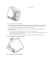
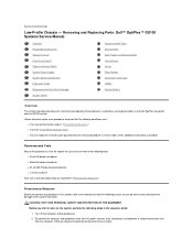
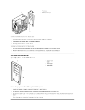
Make sure cables are left inside the slots. Replacing the Low-Profile Computer Cover Check all cable connections, especially those that no tools or extra parts (including screws) are not routed over the drive cage-they do not catch on the computer chassis so that they will prevent the cover from ...
Make sure cables are left inside the slots. Replacing the Low-Profile Computer Cover Check all cable connections, especially those that no tools or extra parts (including screws) are not routed over the drive cage-they do not catch on the computer chassis so that they will prevent the cover from ...
User Guide
Page 78
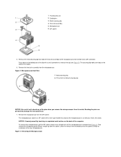
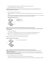
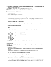
... until the microprocessor is ready for installation of the socket. 6. Figure 4. Figure 3. Then remove the microprocessor by touching an unpainted metal surface on the folded part of the clip with a lever-type handle that holds the heat sink assembly to the microprocessor zero insertion force (ZIF) connector. Remove the heat sink...
... until the microprocessor is ready for installation of the socket. 6. Figure 4. Figure 3. Then remove the microprocessor by touching an unpainted metal surface on the folded part of the clip with a lever-type handle that holds the heat sink assembly to the microprocessor zero insertion force (ZIF) connector. Remove the heat sink...

User Guide
Page 92
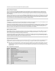
... devices. Video DAC Snoop Video DAC Snoop lets you correct video problems that may occur when you are using a PS/2-compatible keyboard and mouse. As part of the keys. Diskette Interface Diskette Interface controls the operation of each key. PC Speaker PC Speaker determines whether the integrated speaker is turned off...
... devices. Video DAC Snoop Video DAC Snoop lets you correct video problems that may occur when you are using a PS/2-compatible keyboard and mouse. As part of the keys. Diskette Interface Diskette Interface controls the operation of each key. PC Speaker PC Speaker determines whether the integrated speaker is turned off...
User Guide
Page 97
... called device drivers can change the address of one of conflict, check the documentation for the default IRQ-line setting for use of all or part of conflict, you can also cause problems with this problem. To resolve this type of these TSR programs. Typically, your operating system's start-up files...
... called device drivers can change the address of one of conflict, check the documentation for the default IRQ-line setting for use of all or part of conflict, you can also cause problems with this problem. To resolve this type of these TSR programs. Typically, your operating system's start-up files...
Service Manual
Page 1
...and cautions, and they are trademarks of Dell Computer Corporation is subject to change without the written permission of Dell Computer Corporation. Initial release: May 1999 Last revised: 24 Aug 2000 Removing and Replacing Parts Notes, Notices, and Cautions Throughout this ..., may be accompanied by an icon and printed in bold type or in italic type. Dell Computer Corporation disclaims any manner whatsoever without notice. © 1999-2000 Dell Computer Corporation. Dell™ OptiPlex™ GX100 Systems Service Manual Small-Form-Factor Chassis - Removing and Replacing...
...and cautions, and they are trademarks of Dell Computer Corporation is subject to change without the written permission of Dell Computer Corporation. Initial release: May 1999 Last revised: 24 Aug 2000 Removing and Replacing Parts Notes, Notices, and Cautions Throughout this ..., may be accompanied by an icon and printed in bold type or in italic type. Dell Computer Corporation disclaims any manner whatsoever without notice. © 1999-2000 Dell Computer Corporation. Dell™ OptiPlex™ GX100 Systems Service Manual Small-Form-Factor Chassis - Removing and Replacing...
Service Manual
Page 2
... cover. Disconnect the computer and peripherals from ESD. l You can replace or reinstall a part by performing the removal procedure in the Dell OptiPlex low-profile chassis GX100 system. Turn off the computer and all peripherals. 2. Doing so reduces the potential for ...inch nut driver Also, use of one or more of the following steps in "Precautionary Measures." Removing and Replacing Parts: Dell™ OptiPlex™ GX100 Systems Service Manual Overview Precautionary Measures Computer Cover Front-Panel Inserts Chassis Intrusion Switch System Power Supply System Board Components ...
... cover. Disconnect the computer and peripherals from ESD. l You can replace or reinstall a part by performing the removal procedure in the Dell OptiPlex low-profile chassis GX100 system. Turn off the computer and all peripherals. 2. Doing so reduces the potential for ...inch nut driver Also, use of one or more of the following steps in "Precautionary Measures." Removing and Replacing Parts: Dell™ OptiPlex™ GX100 Systems Service Manual Overview Precautionary Measures Computer Cover Front-Panel Inserts Chassis Intrusion Switch System Power Supply System Board Components ...
Service Manual
Page 5
..., use your thumbs to the bezel. When these clips are released, the buttons come free from the bezel. Lay the computer cover on the plastic part of the cover. To remove the 3.5-inch diskette-drive eject button, pull gently on a flat work surface, with the front facing you. 2. Control Panel Removal...
..., use your thumbs to the bezel. When these clips are released, the buttons come free from the bezel. Lay the computer cover on the plastic part of the cover. To remove the 3.5-inch diskette-drive eject button, pull gently on a flat work surface, with the front facing you. 2. Control Panel Removal...
Service Manual
Page 15
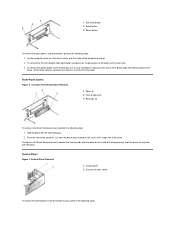
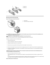
... straight out until the chip is released (see Figure 24). Microprocessor Chip Removal Your microprocessor socket is ready for the new microprocessor. NOTE: Dell recommends that the socket is a zero insertion force (ZIF) socket with a small screwdriver to cool before you touch it from the socket...the computer cover. 2. Press down on the sides of the heat sink assembly. The securing clip hooks over tabs on the folded part of the pins when removing the microprocessor chip from its socket. Leave the release lever extended so that only a technically knowledgeable person ...
... straight out until the chip is released (see Figure 24). Microprocessor Chip Removal Your microprocessor socket is ready for the new microprocessor. NOTE: Dell recommends that the socket is a zero insertion force (ZIF) socket with a small screwdriver to cool before you touch it from the socket...the computer cover. 2. Press down on the sides of the heat sink assembly. The securing clip hooks over tabs on the folded part of the pins when removing the microprocessor chip from its socket. Leave the release lever extended so that only a technically knowledgeable person ...
Service Manual
Page 19
...file require the use a wrist grounding strap as explained in the Dell OptiPlex mini tower chassis GX100 system. Turn off the computer and all peripherals. 2. l You can replace or reinstall a part by performing the removal procedure in "Precautionary Measures." CAUTION: FOR ... Recommended Tools Most of the following conditions exist: l You have removed the computer cover. Removing and Replacing Parts: Dell™ OptiPlex™ GX100 Systems Service Manual Overview Precautionary Measures Computer Cover Eject, Power, and Reset Buttons Control Panel Drives Riser Boards ...
...file require the use a wrist grounding strap as explained in the Dell OptiPlex mini tower chassis GX100 system. Turn off the computer and all peripherals. 2. l You can replace or reinstall a part by performing the removal procedure in "Precautionary Measures." CAUTION: FOR ... Recommended Tools Most of the following conditions exist: l You have removed the computer cover. Removing and Replacing Parts: Dell™ OptiPlex™ GX100 Systems Service Manual Overview Precautionary Measures Computer Cover Eject, Power, and Reset Buttons Control Panel Drives Riser Boards ...
Service Manual
Page 22
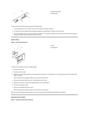
... To remove the eject, power, and reset buttons, perform the following steps: 1. Eject, Power, and Reset Buttons Figure 6. Lay the front bezel on the plastic part of the bezel facing up. 2. 1 Tab release 2 Retaining hooks (2) To remove the front bezel, perform the following steps: 1. When these clips are released, the buttons...
... To remove the eject, power, and reset buttons, perform the following steps: 1. Eject, Power, and Reset Buttons Figure 6. Lay the front bezel on the plastic part of the bezel facing up. 2. 1 Tab release 2 Retaining hooks (2) To remove the front bezel, perform the following steps: 1. When these clips are released, the buttons...
Service Manual
Page 37
... microprocessor chip with the holes in the socket Be careful not to release the clip (see Figure 33). If the release lever on the folded part of the pins when unpacking the microprocessor.
... microprocessor chip with the holes in the socket Be careful not to release the clip (see Figure 33). If the release lever on the folded part of the pins when unpacking the microprocessor.
Service Manual
Page 41
Removing and Replacing Parts: Dell™ OptiPlex™ GX100 Systems Service Manual Overview Precautionary Measures Computer Cover Control Panel Drives Riser Board Expansion-Card Cage DIMMs System Battery Recommended ... "Precautionary Measures." Also, disconnect any procedures in reverse order unless additional information is provided. l You have performed the steps in the Dell OptiPlex small-formfactor chassis GX100 system. CAUTION: FOR YOUR PERSONAL SAFETY AND PROTECTION OF THE EQUIPMENT Before you are disconnecting a peripheral from the computer or are removing...
Removing and Replacing Parts: Dell™ OptiPlex™ GX100 Systems Service Manual Overview Precautionary Measures Computer Cover Control Panel Drives Riser Board Expansion-Card Cage DIMMs System Battery Recommended ... "Precautionary Measures." Also, disconnect any procedures in reverse order unless additional information is provided. l You have performed the steps in the Dell OptiPlex small-formfactor chassis GX100 system. CAUTION: FOR YOUR PERSONAL SAFETY AND PROTECTION OF THE EQUIPMENT Before you are disconnecting a peripheral from the computer or are removing...
Service Manual
Page 44
... cable connector from the bezel. When you remove it from the chassis. 4. To remove the 3.5-inch diskette-drive eject button, pull gently on the plastic part of the PANEL connector). Remove the control panel from the control panel connector on a flat work surface, with the inside of the control panel behind...
... cable connector from the bezel. When you remove it from the chassis. 4. To remove the 3.5-inch diskette-drive eject button, pull gently on the plastic part of the PANEL connector). Remove the control panel from the control panel connector on a flat work surface, with the inside of the control panel behind...
Service Manual
Page 56
NOTE: Dell recommends that secures the heat sink to the microprocessor socket. Remove the screws securing the fan to bend any of the heat sink assembly. Leave ... on the system board. 3. Then remove the fan. 5. Remove the metal clip that only a technically knowledgeable person perform this procedure. Press down on the folded part of the chip and socket aligned, align the pins on the sides of the computer. Align the pin-1 corner of the microprocessor chip with the...
NOTE: Dell recommends that secures the heat sink to the microprocessor socket. Remove the screws securing the fan to bend any of the heat sink assembly. Leave ... on the system board. 3. Then remove the fan. 5. Remove the metal clip that only a technically knowledgeable person perform this procedure. Press down on the folded part of the chip and socket aligned, align the pins on the sides of the computer. Align the pin-1 corner of the microprocessor chip with the...

