
Setup and Quick Reference Guide
Page 7
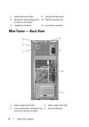
Front View 1 2 34 5 6 7 8 9 12 10 11 1 hard drive activity light 3 WiFi (optional) light 5 power button, power light 2 link integrity light 4 diagnostic lights 6 optical drive About Your Computer 7 About Your Computer Mini Tower -
Front View 1 2 34 5 6 7 8 9 12 10 11 1 hard drive activity light 3 WiFi (optional) light 5 power button, power light 2 link integrity light 4 diagnostic lights 6 optical drive About Your Computer 7 About Your Computer Mini Tower -
Setup and Quick Reference Guide
Page 8
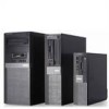
Back View 3 4 2 5 1 6 7 1 power supply check button 2 power supply check light 3 cover-release latch and padlock ring 4 security cable slot (security screw also an option) 8 About Your Computer 7 optical-drive eject button 8 optical-drive filler panel 9 flex bay (for optional floppy drive 10 USB 2.0 connectors (4) or memory card reader) 11 headphone connector 12 microphone connector Mini Tower -
Back View 3 4 2 5 1 6 7 1 power supply check button 2 power supply check light 3 cover-release latch and padlock ring 4 security cable slot (security screw also an option) 8 About Your Computer 7 optical-drive eject button 8 optical-drive filler panel 9 flex bay (for optional floppy drive 10 USB 2.0 connectors (4) or memory card reader) 11 headphone connector 12 microphone connector Mini Tower -

Setup and Quick Reference Guide
Page 9
5 power connector 7 expansion-card slots (4) 6 back-panel connectors Mini Tower - Back Panel Connectors 1 2 3 4 5 6 7 8 14 13 12 11 9 10 1 PS2 mouse connector 3 serial connector 5 network adapter connector 7 space for optional wireless connector 9 line-in/microphone connector 11 VGA video connector 13 DisplayPort connector 2 parallel (printer) connector 4 network-activity light 6 link-integrity light 8 line-out connector 10 USB 2.0 connectors (6) 12 eSATA connector 14 PS2 keyboard connector About Your Computer 9
5 power connector 7 expansion-card slots (4) 6 back-panel connectors Mini Tower - Back Panel Connectors 1 2 3 4 5 6 7 8 14 13 12 11 9 10 1 PS2 mouse connector 3 serial connector 5 network adapter connector 7 space for optional wireless connector 9 line-in/microphone connector 11 VGA video connector 13 DisplayPort connector 2 parallel (printer) connector 4 network-activity light 6 link-integrity light 8 line-out connector 10 USB 2.0 connectors (6) 12 eSATA connector 14 PS2 keyboard connector About Your Computer 9
Setup and Quick Reference Guide
Page 10
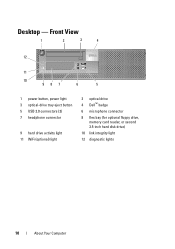
Front View 1 2 3 4 12 11 10 987 6 5 1 power button, power light 3 optical-drive tray eject button 5 USB 2.0 connectors (2) 7 headphone connector 9 hard drive activity light 11 WiFi (optional) light 2 optical drive 4 Dell™ badge 6 microphone connector 8 flex bay (for optional floppy drive, memory card reader, or second 3.5-inch hard disk drive) 10 link integrity light 12 diagnostic lights 10 About Your Computer Desktop -
Front View 1 2 3 4 12 11 10 987 6 5 1 power button, power light 3 optical-drive tray eject button 5 USB 2.0 connectors (2) 7 headphone connector 9 hard drive activity light 11 WiFi (optional) light 2 optical drive 4 Dell™ badge 6 microphone connector 8 flex bay (for optional floppy drive, memory card reader, or second 3.5-inch hard disk drive) 10 link integrity light 12 diagnostic lights 10 About Your Computer Desktop -
Setup and Quick Reference Guide
Page 11
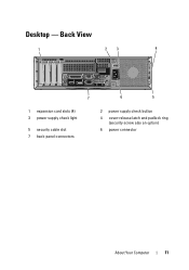
Back View 1 23 4 7 6 5 1 expansion card slots (4) 3 power supply check light 5 security cable slot 7 back-panel connectors 2 power supply check button 4 cover-release latch and padlock ring (security screw also an option) 6 power connector About Your Computer 11 Desktop -
Back View 1 23 4 7 6 5 1 expansion card slots (4) 3 power supply check light 5 security cable slot 7 back-panel connectors 2 power supply check button 4 cover-release latch and padlock ring (security screw also an option) 6 power connector About Your Computer 11 Desktop -

Setup and Quick Reference Guide
Page 12
Desktop - Back Panel Connectors 6 1 2 3 4 5 7 8 14 13 12 1 PS2 mouse connector 3 serial connector 5 network adapter connector 7 space for optional wireless connector 9 line-in/microphone connector 11 VGA video connector 13 DisplayPort connector 9 11 10 2 parallel (printer) connector 4 network-activity light 6 link-integrity light 8 line-out connector 10 USB 2.0 connectors (6) 12 eSATA connector 14 PS2 keyboard connector 12 About Your Computer
Desktop - Back Panel Connectors 6 1 2 3 4 5 7 8 14 13 12 1 PS2 mouse connector 3 serial connector 5 network adapter connector 7 space for optional wireless connector 9 line-in/microphone connector 11 VGA video connector 13 DisplayPort connector 9 11 10 2 parallel (printer) connector 4 network-activity light 6 link-integrity light 8 line-out connector 10 USB 2.0 connectors (6) 12 eSATA connector 14 PS2 keyboard connector 12 About Your Computer
Setup and Quick Reference Guide
Page 13
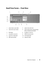
Front View 1 2 3 4 12 11 10 9 8 76 5 1 power button, power light 3 optical-drive eject button 5 Dell badge 7 microphone connector 9 hard drive activity light 11 WiFi (optional) light 2 optical-drive (slim-line) 4 slim-line flex bay (for optional floppy drive or memory card reader) 6 headphone connector 8 USB 2.0 connectors (2) 10 link integrity light 12 diagnostic lights About Your Computer 13 Small Form Factor-
Front View 1 2 3 4 12 11 10 9 8 76 5 1 power button, power light 3 optical-drive eject button 5 Dell badge 7 microphone connector 9 hard drive activity light 11 WiFi (optional) light 2 optical-drive (slim-line) 4 slim-line flex bay (for optional floppy drive or memory card reader) 6 headphone connector 8 USB 2.0 connectors (2) 10 link integrity light 12 diagnostic lights About Your Computer 13 Small Form Factor-

Setup and Quick Reference Guide
Page 14
Small Form Factor- Back View 1 2 3 4 1 expansion-card slots (2) 3 power supply check light 5 security cable slot 7 back-panel connectors 5 7 6 2 power supply check button 4 cover-release latch and padlock ring (security screw also an option) 6 power connector 14 About Your Computer
Small Form Factor- Back View 1 2 3 4 1 expansion-card slots (2) 3 power supply check light 5 security cable slot 7 back-panel connectors 5 7 6 2 power supply check button 4 cover-release latch and padlock ring (security screw also an option) 6 power connector 14 About Your Computer

Setup and Quick Reference Guide
Page 15
Back Panel Connectors 1 2 3 4 5 6 7 8 14 13 12 1 PS2 mouse connector 3 serial connector 5 network adapter connector 7 space for optional wireless connector 9 line-in/microphone connector 11 VGA video connector 13 DisplayPort connector 9 11 10 2 parallel (printer) connector 4 network-activity light 6 link-integrity light 8 line-out connector 10 USB 2.0 connectors (6) 12 eSATA connector 14 PS2 keyboard connector About Your Computer 15 Small Form Factor-
Back Panel Connectors 1 2 3 4 5 6 7 8 14 13 12 1 PS2 mouse connector 3 serial connector 5 network adapter connector 7 space for optional wireless connector 9 line-in/microphone connector 11 VGA video connector 13 DisplayPort connector 9 11 10 2 parallel (printer) connector 4 network-activity light 6 link-integrity light 8 line-out connector 10 USB 2.0 connectors (6) 12 eSATA connector 14 PS2 keyboard connector About Your Computer 15 Small Form Factor-
Setup and Quick Reference Guide
Page 34
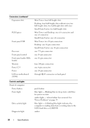
solid blue for power-on page 39. blue light - See "Power Problems" on state amber light - Blinking blue in sleep state; A blinking blue light indicates the computer is reading data from or writing data to the SATA hard drive or CD/DVD. A boot failure has occurred. ...Processor Front panel control Front panel audio HDA header Memory Power 12 V Power LAN on motherboard (LOM) Controls and Lights Front of computer: Power button Power light Drive activity light Diagnostic light Mini Tower: four full-height slots Desktop: four half-height slots without riser, two full-height slots, two half...
solid blue for power-on page 39. blue light - See "Power Problems" on state amber light - Blinking blue in sleep state; A blinking blue light indicates the computer is reading data from or writing data to the SATA hard drive or CD/DVD. A boot failure has occurred. ...Processor Front panel control Front panel audio HDA header Memory Power 12 V Power LAN on motherboard (LOM) Controls and Lights Front of computer: Power button Power light Drive activity light Diagnostic light Mini Tower: four full-height slots Desktop: four half-height slots without riser, two full-height slots, two half...

Setup and Quick Reference Guide
Page 35
... power system by using the power supply wattage rating. Controls and Lights (continued) Network link light blue WiFi (optional) link light blue Rear of the computer) and the electrical outlet. If the LED does not light up, the power supply may be connected during this test. Green..., 100 - Orange, 1000 - Specifications 35 Network activity light (on the link speed: integrated network adapter) 10 - When the system...
... power system by using the power supply wattage rating. Controls and Lights (continued) Network link light blue WiFi (optional) link light blue Rear of the computer) and the electrical outlet. If the LED does not light up, the power supply may be connected during this test. Green..., 100 - Orange, 1000 - Specifications 35 Network activity light (on the link speed: integrated network adapter) 10 - When the system...

Setup and Quick Reference Guide
Page 39
...and fix the problem(s). • If an error message occurs in a program, see www.dell.com/regulatory_compliance. For additional safety best practices information, see the program documentation. The diagnostic lights on the front of the computer along with the status of a power problem. Consult the ... In the search results, select the option that the device is correctly installed. • If an error message appears on support.dell.com. Troubleshooting Tips 39 Tips • If a device does not work, ensure that best describes the problem and follow the remaining troubleshooting ...
...and fix the problem(s). • If an error message occurs in a program, see www.dell.com/regulatory_compliance. For additional safety best practices information, see the program documentation. The diagnostic lights on the front of the computer along with the status of a power problem. Consult the ... In the search results, select the option that the device is correctly installed. • If an error message appears on support.dell.com. Troubleshooting Tips 39 Tips • If a device does not work, ensure that best describes the problem and follow the remaining troubleshooting ...

Setup and Quick Reference Guide
Page 40
... extension cables, and other significance. Plug the computer into an electrical outlet and are turned on page 66). 40 Troubleshooting Tips NOTE: The diagnostic lights will blink when the power button is amber or off, and will not when it with another device, such as a lamp. • Ensure... any power strips being used are plugged into a working electrical outlet and press the power button. • If the problem persists, contact Dell (see "Contacting Dell" on . • Ensure that the electrical outlet is working by testing it is either turned off or not receiving power. This has no...
... extension cables, and other significance. Plug the computer into an electrical outlet and are turned on page 66). 40 Troubleshooting Tips NOTE: The diagnostic lights will blink when the power button is amber or off, and will not when it with another device, such as a lamp. • Ensure... any power strips being used are plugged into a working electrical outlet and press the power button. • If the problem persists, contact Dell (see "Contacting Dell" on . • Ensure that the electrical outlet is working by testing it is either turned off or not receiving power. This has no...

Setup and Quick Reference Guide
Page 41
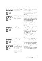
...the computer still fails to the switch illuminates, the problem may be a problem with the motherboard. No CPU present. Contact Dell (see "Contacting Dell" on page 66). 3 If the LED still does not illuminate, remove the PSU connections from the motherboard, then press...could be a problem with a peripheral. Press and hold the power supply button. Troubleshooting Tips 41 Contact Dell (see "Contacting Dell" on the rear of the power supply unit. Light Pattern Blinking Amber Steady Amber Problem Description A possible motherboard, power supply, or peripheral failure has occurred. ...
...the computer still fails to the switch illuminates, the problem may be a problem with the motherboard. No CPU present. Contact Dell (see "Contacting Dell" on page 66). 3 If the LED still does not illuminate, remove the PSU connections from the motherboard, then press...could be a problem with a peripheral. Press and hold the power supply button. Troubleshooting Tips 41 Contact Dell (see "Contacting Dell" on the rear of the power supply unit. Light Pattern Blinking Amber Steady Amber Problem Description A possible motherboard, power supply, or peripheral failure has occurred. ...

Setup and Quick Reference Guide
Page 42
... one memory module is installed, try moving it to boot, inspect the CPU socket for damage. • If the problem persists, contact Dell (see "Contacting Dell" on page 66). Light Pattern Steady Amber Steady Amber Steady Amber Steady Amber Problem Description Suggested Resolution Memory modules are installed, remove the modules, then reinstall one...
... one memory module is installed, try moving it to boot, inspect the CPU socket for damage. • If the problem persists, contact Dell (see "Contacting Dell" on page 66). Light Pattern Steady Amber Steady Amber Steady Amber Steady Amber Problem Description Suggested Resolution Memory modules are installed, remove the modules, then reinstall one...
Setup and Quick Reference Guide
Page 43
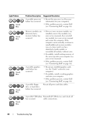
... motherboard failure has occurred. • Remove all internal and external peripherals, and restart the computer. The diagnostic lights are not lit after the computer successfully boots to boot, contact Dell (see "Contacting Dell" on page 66). Light Pattern Steady Amber Steady Amber Steady Amber Steady Amber Steady Blue Problem Description Suggested Resolution Power connector...
... motherboard failure has occurred. • Remove all internal and external peripherals, and restart the computer. The diagnostic lights are not lit after the computer successfully boots to boot, contact Dell (see "Contacting Dell" on page 66). Light Pattern Steady Amber Steady Amber Steady Amber Steady Amber Steady Blue Problem Description Suggested Resolution Power connector...
Setup and Quick Reference Guide
Page 44
... failure has occurred. • Reseat any installed graphics cards (see the "Cards" section for your computer. • If the problem persists, contact Dell (see "Contacting Dell" on page 66). Light Pattern Steady Blue Steady Blue Steady Blue Steady Blue Steady Blue Problem Description A possible processor failure has occurred. If the computer starts normally...
... failure has occurred. • Reseat any installed graphics cards (see the "Cards" section for your computer. • If the problem persists, contact Dell (see "Contacting Dell" on page 66). Light Pattern Steady Blue Steady Blue Steady Blue Steady Blue Steady Blue Problem Description A possible processor failure has occurred. If the computer starts normally...

Setup and Quick Reference Guide
Page 45
...starts normally, continue to install additional memory modules (one module (see your service manual). • If the problem persists, contact Dell (see "Contacting Dell" on page 66). Memory modules are detected, but a memory configuration or compatibility error has occurred. • Ensure that the ... install working memory of the same type into your computer (see your service manual) and restart the computer. Troubleshooting Tips 45 Light Pattern Steady Blue Steady Blue Problem Description Suggested Resolution No memory modules are detected. • If two or more memory modules ...
...starts normally, continue to install additional memory modules (one module (see your service manual). • If the problem persists, contact Dell (see "Contacting Dell" on page 66). Memory modules are detected, but a memory configuration or compatibility error has occurred. • Ensure that the ... install working memory of the same type into your computer (see your service manual) and restart the computer. Troubleshooting Tips 45 Light Pattern Steady Blue Steady Blue Problem Description Suggested Resolution No memory modules are detected. • If two or more memory modules ...
Setup and Quick Reference Guide
Page 46
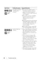
Light Pattern Steady Blue Steady Blue Problem Description Suggested Resolution A possible expansion card failure has occurred. 1 Determine if a conflict exists by removing an expansion card (not a graphics card) and restarting the computer (see the "Cards" section for your computer. • If the problem persists, contact Dell (see "Contacting Dell... • Ensure that all hard drive and optical drive cables are properly connected to the system board (see "Contacting Dell" on your computer). 2 If the problem persists, reinstall the card you removed, then remove a different card and ...
Light Pattern Steady Blue Steady Blue Problem Description Suggested Resolution A possible expansion card failure has occurred. 1 Determine if a conflict exists by removing an expansion card (not a graphics card) and restarting the computer (see the "Cards" section for your computer. • If the problem persists, contact Dell (see "Contacting Dell... • Ensure that all hard drive and optical drive cables are properly connected to the system board (see "Contacting Dell" on your computer). 2 If the problem persists, reinstall the card you removed, then remove a different card and ...
Setup and Quick Reference Guide
Page 47
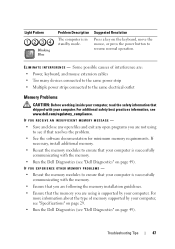
Light Pattern Blinking Blue Problem Description The computer is successfully communicating with the memory. • Run the Dell Diagnostics (see "Dell Diagnostics" on page 49). For additional safety best practices information, see if that your computer is in standby mode. If necessary, install additional memory. • Reseat the memory modules to see www.dell... is successfully communicating with your computer, see "Specifications" on page 29. • Run the Dell Diagnostics (see "Dell Diagnostics" on the keyboard, move the mouse, or press the power button to the same electrical...
Light Pattern Blinking Blue Problem Description The computer is successfully communicating with the memory. • Run the Dell Diagnostics (see "Dell Diagnostics" on page 49). For additional safety best practices information, see if that your computer is in standby mode. If necessary, install additional memory. • Reseat the memory modules to see www.dell... is successfully communicating with your computer, see "Specifications" on page 29. • Run the Dell Diagnostics (see "Dell Diagnostics" on the keyboard, move the mouse, or press the power button to the same electrical...


