
Setup and Quick Reference Guide
Page 7
Front View 1 2 3 4 5 11 10 98 76 1 optical drive 3 USB 2.0 connectors (2) 5 power button, power light 7 network-connectivity light 9 headphone connector 11 floppy drive or Media Card Reader (optional) 2 optical-drive eject button 4 hard-drive activity light 6 diagnostic lights (4) 8 microphone connector 10 optional floppy drive eject button About Your Computer 7 About Your Computer Desktop -
Front View 1 2 3 4 5 11 10 98 76 1 optical drive 3 USB 2.0 connectors (2) 5 power button, power light 7 network-connectivity light 9 headphone connector 11 floppy drive or Media Card Reader (optional) 2 optical-drive eject button 4 hard-drive activity light 6 diagnostic lights (4) 8 microphone connector 10 optional floppy drive eject button About Your Computer 7 About Your Computer Desktop -
Setup and Quick Reference Guide
Page 10
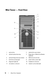
Front View 1 2 3 4 12 5 11 6 10 7 9 8 1 optical drive 3 optional optical drive bay 5 optional floppy drive eject button 7 hard-drive activity light 9 diagnostic lights (4) 11 microphone connector 2 optical-drive eject button 4 floppy drive or Media Card Reader (optional) 6 USB 2.0 connectors (2) 8 power button, power light 10 headphone connector 12 network-connectivity light 10 About Your Computer Mini Tower -
Front View 1 2 3 4 12 5 11 6 10 7 9 8 1 optical drive 3 optional optical drive bay 5 optional floppy drive eject button 7 hard-drive activity light 9 diagnostic lights (4) 11 microphone connector 2 optical-drive eject button 4 floppy drive or Media Card Reader (optional) 6 USB 2.0 connectors (2) 8 power button, power light 10 headphone connector 12 network-connectivity light 10 About Your Computer Mini Tower -

Setup and Quick Reference Guide
Page 13
Front View 1 2 3 4 5 6 11 10 9 8 7 1 optical drive 2 optical-drive eject button 3 USB 2.0 connectors (2) 4 network-connectivity light 5 diagnostic lights (4) 6 hard-drive activity light 7 power button, power light 8 microphone connector 9 headphone connector 10 optional floppy drive eject button 11 floppy drive or Media Card Reader (optional) About Your Computer 13 Small Form Factor -
Front View 1 2 3 4 5 6 11 10 9 8 7 1 optical drive 2 optical-drive eject button 3 USB 2.0 connectors (2) 4 network-connectivity light 5 diagnostic lights (4) 6 hard-drive activity light 7 power button, power light 8 microphone connector 9 headphone connector 10 optional floppy drive eject button 11 floppy drive or Media Card Reader (optional) About Your Computer 13 Small Form Factor -

Setup and Quick Reference Guide
Page 15
Back View 1 2 3 6 1 diagnostic lights (4) 3 security cable slot 5 power connector 5 4 2 cover release knob 4 back-panel connectors 6 air vent About Your Computer 15 Ultra Small Form Factor - Front View 1 2 34 98 1 USB 2.0 connectors (2) 3 hard drive activity light 5 air vents 7 optical drive 9 air vents 76 5 2 microphone connector 4 power button, power light 6 optical-drive eject button 8 headphone connector Ultra Small Form Factor -
Back View 1 2 3 6 1 diagnostic lights (4) 3 security cable slot 5 power connector 5 4 2 cover release knob 4 back-panel connectors 6 air vent About Your Computer 15 Ultra Small Form Factor - Front View 1 2 34 98 1 USB 2.0 connectors (2) 3 hard drive activity light 5 air vents 7 optical drive 9 air vents 76 5 2 microphone connector 4 power button, power light 6 optical-drive eject button 8 headphone connector Ultra Small Form Factor -
Setup and Quick Reference Guide
Page 42
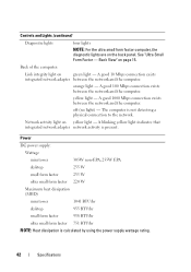
... and the computer. A good 1000 Mbps connection exists between the network and the computer. yellow light - off (no light) - Back of the computer: Link integrity light on the back panel. Power DC power supply: Wattage mini tower 305W non-EPA; 255W EPA... rating. 42 Specifications A blinking yellow light indicates that integrated network adapter network activity is present. A good 10 Mbps connection exists integrated network adapter between the network and the computer. Controls and Lights (continued) Diagnostic lights four lights NOTE: For the ultra small form ...
... and the computer. A good 1000 Mbps connection exists between the network and the computer. yellow light - off (no light) - Back of the computer: Link integrity light on the back panel. Power DC power supply: Wattage mini tower 305W non-EPA; 255W EPA... rating. 42 Specifications A blinking yellow light indicates that integrated network adapter network activity is present. A good 10 Mbps connection exists integrated network adapter between the network and the computer. Controls and Lights (continued) Diagnostic lights four lights NOTE: For the ultra small form ...
Setup and Quick Reference Guide
Page 75
specifications all, 35 audio, 36 connectors, 39 controls and lights, 41 drives, 37 environmental, 44 expansion bus, 36 memory, 35 physical, 43 power, 42 processor, 35 system information, 35 video, 36 support, 65 contacting Dell, 71 DellConnect, 66 online services, 66 regional, 66 technical...Conditions, 64 transferring information to a new computer, 30 troubleshooting, 45, 64 blue screen, 49 computer not responding, 48 Dell Diagnostics, 50 memory, 47 power, 46 power light conditions, 46 program crashes, 48 programs and Windows compatibility, 48 restore to previous state, 56-57 software, 48-49 ...
specifications all, 35 audio, 36 connectors, 39 controls and lights, 41 drives, 37 environmental, 44 expansion bus, 36 memory, 35 physical, 43 power, 42 processor, 35 system information, 35 video, 36 support, 65 contacting Dell, 71 DellConnect, 66 online services, 66 regional, 66 technical...Conditions, 64 transferring information to a new computer, 30 troubleshooting, 45, 64 blue screen, 49 computer not responding, 48 Dell Diagnostics, 50 memory, 47 power, 46 power light conditions, 46 program crashes, 48 programs and Windows compatibility, 48 restore to previous state, 56-57 software, 48-49 ...
Service Manual
Page 133
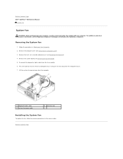
Follow the procedures in the reverse order. Disconnect the diagnostics lights cable from the computer. 1 diagnostic lights cable 3 system fan power cable 2 retention tab Installing the System Fan To replace the fan, follow the removal procedures in... Board). 5. For additional safety best practices information, see Removing the Processor). 4. Removing the System Fan 1. Back to Contents Page Dell™ OptiPlex™ 760 Service Manual System Fan System Fan WARNING: Before working inside your computer. Remove the heat sink assembly and processor (see the Regulatory Compliance...
Follow the procedures in the reverse order. Disconnect the diagnostics lights cable from the computer. 1 diagnostic lights cable 3 system fan power cable 2 retention tab Installing the System Fan To replace the fan, follow the removal procedures in... Board). 5. For additional safety best practices information, see Removing the Processor). 4. Removing the System Fan 1. Back to Contents Page Dell™ OptiPlex™ 760 Service Manual System Fan System Fan WARNING: Before working inside your computer. Remove the heat sink assembly and processor (see the Regulatory Compliance...
Service Manual
Page 161
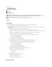
Back to Contents Page Troubleshooting Dell™ OptiPlex™ 760 Service Manual Tools Dell Diagnostics Solving Problems Dell Technical Update Service WARNING: Before working by testing it with your computer. WARNING: Always unplug your computer, read...that the electrical outlet is turned on. ¡ Bypass power protection devices, power strips, and power extension cables to the same electrical outlet Diagnostic Lights System Board Components ¡ Small Form Factor - For additional safety best practices information, see the Regulatory Compliance Homepage on a power strip &#...
Back to Contents Page Troubleshooting Dell™ OptiPlex™ 760 Service Manual Tools Dell Diagnostics Solving Problems Dell Technical Update Service WARNING: Before working by testing it with your computer. WARNING: Always unplug your computer, read...that the electrical outlet is turned on. ¡ Bypass power protection devices, power strips, and power extension cables to the same electrical outlet Diagnostic Lights System Board Components ¡ Small Form Factor - For additional safety best practices information, see the Regulatory Compliance Homepage on a power strip &#...
Service Manual
Page 162
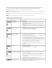
...minute for the power to boot, inspect the processor socket for damage. Blinking Amber No CPU present. Contact Dell (see Contacting Dell). If the power supply diagnostic light still does not illuminate, the problem is working by testing it with another device, such as a lamp....that the main power cable and front panel cable are detected, but a memory power failure has occurred. Contact Dell (see Contacting Dell). Diagnostic Light Codes During POST Light Pattern Off Problem Description The computer is installed, try moving it illuminates, there could be with your computer. ...
...minute for the power to boot, inspect the processor socket for damage. Blinking Amber No CPU present. Contact Dell (see Contacting Dell). If the power supply diagnostic light still does not illuminate, the problem is working by testing it with another device, such as a lamp....that the main power cable and front panel cable are detected, but a memory power failure has occurred. Contact Dell (see Contacting Dell). Diagnostic Light Codes During POST Light Pattern Off Problem Description The computer is installed, try moving it illuminates, there could be with your computer. ...

Service Manual
Page 163
... and restart the computer. Steady Amber Possible peripheral card or motherboard failure has occurred. The diagnostic lights are detected, but the BIOS may be faulty. A possible processor failure has occurred. l If the problem persists, contact Dell (see Contacting Dell). If the computer boots, add the cards back one by one until you find the...
... and restart the computer. Steady Amber Possible peripheral card or motherboard failure has occurred. The diagnostic lights are detected, but the BIOS may be faulty. A possible processor failure has occurred. l If the problem persists, contact Dell (see Contacting Dell). If the computer boots, add the cards back one by one until you find the...
Service Manual
Page 164
...for your computer. Steady Green A possible graphics card failure has occurred. l If the problem persists, contact Dell (see Contacting Dell). The light remains solid or off to install additional memory modules (one module (see the "Cards" section for memory...Reinstall all USB devices and check all power and data cables. Blinking Green Power Supply Diagnostic Light The power supply diagnostic light located on your computer (see Contacting Dell). Indicates no special requirements for your computer). Steady Green A possible USB failure has ...
...for your computer. Steady Green A possible graphics card failure has occurred. l If the problem persists, contact Dell (see Contacting Dell). The light remains solid or off to install additional memory modules (one module (see the "Cards" section for memory...Reinstall all USB devices and check all power and data cables. Blinking Green Power Supply Diagnostic Light The power supply diagnostic light located on your computer (see Contacting Dell). Indicates no special requirements for your computer). Steady Green A possible USB failure has ...

Service Manual
Page 172
...to access the Task Manager. 2. See Hardware Troubleshooter. See Diagnostic Lights. Click to select the program that the keyboard cable is no longer responding. 4. Contact Dell (see the Regulatory Compliance Homepage on www.dell.com at least 8 to the computer. Contact the IEEE ...you are unable to get a response by Dell - l Shut down the computer (see the Regulatory Compliance Homepage on www.dell.com at www.dell.com/regulatory_compliance. The computer does not start up Check the diagnostic lights - Ensure that shipped with a Dell IEEE 1394 device - A program stops ...
...to access the Task Manager. 2. See Hardware Troubleshooter. See Diagnostic Lights. Click to select the program that the keyboard cable is no longer responding. 4. Contact Dell (see the Regulatory Compliance Homepage on www.dell.com at least 8 to the computer. Contact the IEEE ...you are unable to get a response by Dell - l Shut down the computer (see the Regulatory Compliance Homepage on www.dell.com at www.dell.com/regulatory_compliance. The computer does not start up Check the diagnostic lights - Ensure that shipped with a Dell IEEE 1394 device - A program stops ...

Service Manual
Page 174
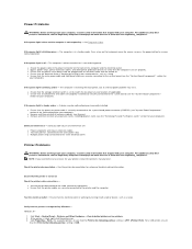
... the mouse. l Ensure that you are following the memory installation guidelines (see Installing Memory Module (s)). l Run the Dell Diagnostics (see the Regulatory Compliance Homepage on the back of the computer and the network jack. Mouse Problems WARNING: Before working...1. Reinstall the mouse driver Run the Hardware Troubleshooter - For additional safety best practices information, see Dell Diagnostics). Check the network lights on www.dell.com at www.dell.com/regulatory_compliance. Restart the computer and log on the setup diagram for bent or broken pins. ...
... the mouse. l Ensure that you are following the memory installation guidelines (see Installing Memory Module (s)). l Run the Dell Diagnostics (see the Regulatory Compliance Homepage on the back of the computer and the network jack. Mouse Problems WARNING: Before working...1. Reinstall the mouse driver Run the Hardware Troubleshooter - For additional safety best practices information, see Dell Diagnostics). Check the network lights on www.dell.com at www.dell.com/regulatory_compliance. Restart the computer and log on the setup diagram for bent or broken pins. ...
Service Manual
Page 175
...safety best practices information, see the "System Board Components" section for cable connection information. If the power light is blue and the computer is blinking amber - A device may exist. Check the printer documentation -...dell.com/regulatory_compliance. The computer is USB. l Ensure that all memory modules (see the Regulatory Compliance Homepage on the back of the computer and the electrical outlet. Test the electrical outlet - Power Problems WARNING: Before working inside your computer, read the safety information that shipped with your computer. See Diagnostic Lights...
...safety best practices information, see the "System Board Components" section for cable connection information. If the power light is blue and the computer is blinking amber - A device may exist. Check the printer documentation -...dell.com/regulatory_compliance. The computer is USB. l Ensure that all memory modules (see the Regulatory Compliance Homepage on the back of the computer and the electrical outlet. Test the electrical outlet - Power Problems WARNING: Before working inside your computer, read the safety information that shipped with your computer. See Diagnostic Lights...
Service Manual
Page 177
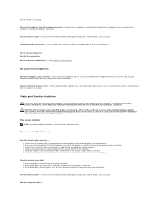
...computer came with a PCI graphics card installed, removal of the card is defective. Ensure that the monitor cable is connected to support.dell.com. Eliminate possible interference - For additional safety best practices information, see the monitor's documentation. however, the card is lit or... if the monitor's power cable is not necessary when installing additional graphics cards; Run the speaker diagnostics Reinstall the sound driver Run the Hardware Troubleshooter - Click or double-click the speaker icon in a safe and secure location. Check the diagnostic lights -
...computer came with a PCI graphics card installed, removal of the card is defective. Ensure that the monitor cable is connected to support.dell.com. Eliminate possible interference - For additional safety best practices information, see the monitor's documentation. however, the card is lit or... if the monitor's power cable is not necessary when installing additional graphics cards; Run the speaker diagnostics Reinstall the sound driver Run the Hardware Troubleshooter - Click or double-click the speaker icon in a safe and secure location. Check the diagnostic lights -

Service Manual
Page 178
... display settings - Shut down your computer and connect an external monitor to Contents Page Dell Technical Update Service The Dell Technical Update service provides proactive e-mail notification of the display is readable Connect an external...Click the area you receive notifications. Windows Vista: 1. Only part of software and hardware updates for the Dell Technical Update service, go to check for instructions on adjusting the contrast and brightness, demagnetizing (degaussing) ...service is poor Check the graphics card power cable connection - See Diagnostic Lights.
... display settings - Shut down your computer and connect an external monitor to Contents Page Dell Technical Update Service The Dell Technical Update service provides proactive e-mail notification of the display is readable Connect an external...Click the area you receive notifications. Windows Vista: 1. Only part of software and hardware updates for the Dell Technical Update service, go to check for instructions on adjusting the contrast and brightness, demagnetizing (degaussing) ...service is poor Check the graphics card power cable connection - See Diagnostic Lights.
Technical Guide
Page 4
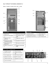
DELL™ OPTIPLEX™ 760 TECHNICAL GUIDEBOOK V1.0 MINI TOWER COMPUTER (MT) VIEW FRONT VIEW 1 Optical Drive 2 Optical Drive Eject Button 3 Optical Drive Bay (optional) 4 Floppy Drive or Media Card Reader (0ptional) 5 Optional Floppy Drive Eject Button 6 USB 2.0 Connectors (2) 7 Hard Drive Activity Light 8 Power Button, Power Light 9 Diagnostic Lights (4) 10 Headphone Connector 11 Microphone Connector 12 Network Connectivity...
DELL™ OPTIPLEX™ 760 TECHNICAL GUIDEBOOK V1.0 MINI TOWER COMPUTER (MT) VIEW FRONT VIEW 1 Optical Drive 2 Optical Drive Eject Button 3 Optical Drive Bay (optional) 4 Floppy Drive or Media Card Reader (0ptional) 5 Optional Floppy Drive Eject Button 6 USB 2.0 Connectors (2) 7 Hard Drive Activity Light 8 Power Button, Power Light 9 Diagnostic Lights (4) 10 Headphone Connector 11 Microphone Connector 12 Network Connectivity...

Technical Guide
Page 5
DELL™ OPTIPLEX™ 760 TECHNICAL GUIDEBOOK V1.0 DESKTOP COMPUTER (DT) VIEW FRONT VIEW 1 Optical Drive 2 Optical Drive Eject Button 7 Network Connectivity Light 8 Microphone Connector 3 USB 2.0 Connectors (2) 9 Headphone Connector 4 Hard Drive Activity Light 10 Optional Floppy Drive Eject Button 5 Power Button, Power Light 11 Floppy Drive or Media Card Reader (optional) 6 Diagnostic Lights (4) BACK VIEW 1 Expansion Card Slots (3) 2 Air...
DELL™ OPTIPLEX™ 760 TECHNICAL GUIDEBOOK V1.0 DESKTOP COMPUTER (DT) VIEW FRONT VIEW 1 Optical Drive 2 Optical Drive Eject Button 7 Network Connectivity Light 8 Microphone Connector 3 USB 2.0 Connectors (2) 9 Headphone Connector 4 Hard Drive Activity Light 10 Optional Floppy Drive Eject Button 5 Power Button, Power Light 11 Floppy Drive or Media Card Reader (optional) 6 Diagnostic Lights (4) BACK VIEW 1 Expansion Card Slots (3) 2 Air...
Technical Guide
Page 6
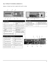
DELL™ OPTIPLEX™ 760 TECHNICAL GUIDEBOOK V1.0 SMALL FORM FACTOR COMPUTER (SFF) VIEW FRONT VIEW 1 Optical Drive 2 Optical Drive Eject Button 7 Power Button, Power Light 8 Microphone Connector 3 USB 2.0 Connectors (2) 9 Headphone Connector 4 Network Connectivity Light 10 Optional Floppy Drive Eject Button 5 Diagnostic Lights (4) 11 Floppy Drive or Media Card Reader (optional) 6 Hard Drive Activity Light BACK VIEW 1 Padlock Rings...
DELL™ OPTIPLEX™ 760 TECHNICAL GUIDEBOOK V1.0 SMALL FORM FACTOR COMPUTER (SFF) VIEW FRONT VIEW 1 Optical Drive 2 Optical Drive Eject Button 7 Power Button, Power Light 8 Microphone Connector 3 USB 2.0 Connectors (2) 9 Headphone Connector 4 Network Connectivity Light 10 Optional Floppy Drive Eject Button 5 Diagnostic Lights (4) 11 Floppy Drive or Media Card Reader (optional) 6 Hard Drive Activity Light BACK VIEW 1 Padlock Rings...
Technical Guide
Page 7
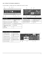
DELL™ OPTIPLEX™ 760 TECHNICAL GUIDEBOOK V1.0 ULTRA SMALL FORM FACTOR COMPUTER (USFF) VIEW FRONT VIEW 1 USB 2.0 Connectors (2) 6 Optical Drive Eject Button 2 Hard Drive Activity Light 7 Optical Drive 3 USB 2.0 Connectors (2) 8 Headphone Connector 4 Power Button, Power Light 5 Air Vents 9 Air Vents BACK VIEW 1 Diagnostic Lights (4) 2 Cover Release Knob 3 Security Cable Slot 4 Back-Panel Connector 5 Power Connector 6 Air Vent...
DELL™ OPTIPLEX™ 760 TECHNICAL GUIDEBOOK V1.0 ULTRA SMALL FORM FACTOR COMPUTER (USFF) VIEW FRONT VIEW 1 USB 2.0 Connectors (2) 6 Optical Drive Eject Button 2 Hard Drive Activity Light 7 Optical Drive 3 USB 2.0 Connectors (2) 8 Headphone Connector 4 Power Button, Power Light 5 Air Vents 9 Air Vents BACK VIEW 1 Diagnostic Lights (4) 2 Cover Release Knob 3 Security Cable Slot 4 Back-Panel Connector 5 Power Connector 6 Air Vent...


