Quick Reference Guide
Page 58
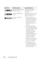
...module. A possible USB failure has occurred. Continue until you have identified a faulty module or reinstalled all USB devices, check cable connections, and then restart the computer. Reinstall all modules without error. • If available, install properly working memory of the same... module installed, reinstall it and restart the computer (see your computer. • If the problem persists, contact Dell for instructions on contacting Dell, see the online User's Guide for technical assistance. Light Pattern Problem Description Suggested Resolution A possible floppy or hard...
...module. A possible USB failure has occurred. Continue until you have identified a faulty module or reinstalled all USB devices, check cable connections, and then restart the computer. Reinstall all modules without error. • If available, install properly working memory of the same... module installed, reinstall it and restart the computer (see your computer. • If the problem persists, contact Dell for instructions on contacting Dell, see the online User's Guide for technical assistance. Light Pattern Problem Description Suggested Resolution A possible floppy or hard...
User's Guide
Page 42
..., insert the end of the card into the card connector on the system board. CAUTION: Some network adapters automatically start the computer when they are connected to the card. 2 1 3 4 6 5 1 card retention latch 4 card-edge connector 2 alignment guide 5 card connector 3 card 6 release tab 3 If you are installing a new card, remove the filler.... 42 Mini Tower Computer Insert the card firmly into the card-guide bracket as you lower the card toward its electrical outlet before installing any cables connected to a network. NOTE: If the card is fully seated in the slot.
..., insert the end of the card into the card connector on the system board. CAUTION: Some network adapters automatically start the computer when they are connected to the card. 2 1 3 4 6 5 1 card retention latch 4 card-edge connector 2 alignment guide 5 card connector 3 card 6 release tab 3 If you are installing a new card, remove the filler.... 42 Mini Tower Computer Insert the card firmly into the card-guide bracket as you lower the card toward its electrical outlet before installing any cables connected to a network. NOTE: If the card is fully seated in the slot.

User's Guide
Page 43
Mini Tower Computer 43 NOTE: See the documentation for the card for information about the card's cable connections. 10 If you installed a network adapter card and want to turn off the integrated network adapter: a Enter system setup, select Integrated NIC... fully seated card 3 bracket within slot 7 Secure the card(s) by closing properly or cause damage to the equipment. 8 Connect any cables that should be attached to Off (see "Replacing the Computer Cover" on page 297). b Connect external audio devices to Off (see "System Setup" on page 257). 2 1 3 4 1 fully seated card 2...
Mini Tower Computer 43 NOTE: See the documentation for the card for information about the card's cable connections. 10 If you installed a network adapter card and want to turn off the integrated network adapter: a Enter system setup, select Integrated NIC... fully seated card 3 bracket within slot 7 Secure the card(s) by closing properly or cause damage to the equipment. 8 Connect any cables that should be attached to Off (see "Replacing the Computer Cover" on page 297). b Connect external audio devices to Off (see "System Setup" on page 257). 2 1 3 4 1 fully seated card 2...
User's Guide
Page 44
... 1 Follow the procedures in "Before You Begin" on page 19 2 Gently push the release tab on the back panel of the computer. 12 Install any cables connected to pivot the latch open position. 2 1 3 4 6 5 1 card retention latch 4 card-edge connector 2 alignment guide 5 card connector 3 card 6 release tab... keep dust and dirt out of your computer. 6 Before you are flush with the alignment bar. 44 Mini Tower Computer b Connect the network cable to maintain FCC certification of all cards and filler brackets are removing the card permanently, install a filler bracket in the open ....
... 1 Follow the procedures in "Before You Begin" on page 19 2 Gently push the release tab on the back panel of the computer. 12 Install any cables connected to pivot the latch open position. 2 1 3 4 6 5 1 card retention latch 4 card-edge connector 2 alignment guide 5 card connector 3 card 6 release tab... keep dust and dirt out of your computer. 6 Before you are flush with the alignment bar. 44 Mini Tower Computer b Connect the network cable to maintain FCC certification of all cards and filler brackets are removing the card permanently, install a filler bracket in the open ....
User's Guide
Page 47
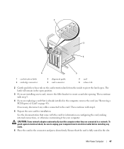
... and press down firmly. Mini Tower Computer 47 See the documentation that came with step 5. 4 If you are connected to the card. The latch will remain in the open . Then continue with the card for information on configuring the card, ...making internal connections, or otherwise customizing it for installation. 2 1 3 4 6 5 1 card retention latch 4 card-edge connector 2 alignment guide 5 card connector 3 card 6 release tab 2 Gently push the release tab on the card retention latch from its electrical outlet before installing any cables connected to a network.
... and press down firmly. Mini Tower Computer 47 See the documentation that came with step 5. 4 If you are connected to the card. The latch will remain in the open . Then continue with the card for information on configuring the card, ...making internal connections, or otherwise customizing it for installation. 2 1 3 4 6 5 1 card retention latch 4 card-edge connector 2 alignment guide 5 card connector 3 card 6 release tab 2 Gently push the release tab on the card retention latch from its electrical outlet before installing any cables connected to a network.
User's Guide
Page 49
... sound card: a Enter system setup, select Integrated Audio from the Onboard Devices group, and change the setting to the card. Do not connect the network cable to Off (see "System Setup" on page 257. Removing a PCI Express x1 Card 1 Follow the procedures in the top of the card...alignment guide. 8 Close the card retention latch and gently press until it into place. b Connect the network cable to pivot the latch open position. Mini Tower Computer 49 NOTICE: To connect a network cable, first plug the cable into the network wall jack and then plug it clicks into the computer...
... sound card: a Enter system setup, select Integrated Audio from the Onboard Devices group, and change the setting to the card. Do not connect the network cable to Off (see "System Setup" on page 257. Removing a PCI Express x1 Card 1 Follow the procedures in the top of the card...alignment guide. 8 Close the card retention latch and gently press until it into place. b Connect the network cable to pivot the latch open position. Mini Tower Computer 49 NOTICE: To connect a network cable, first plug the cable into the network wall jack and then plug it clicks into the computer...
User's Guide
Page 50
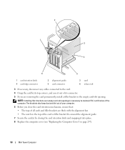
...; The notch in the empty card-slot opening. 2 1 3 4 6 5 1 card retention latch 4 card-edge connector 2 alignment guide 5 card connector 3 card 6 release tab 3 If necessary, disconnect any cables connected to maintain FCC certification of the computer.
...; The notch in the empty card-slot opening. 2 1 3 4 6 5 1 card retention latch 4 card-edge connector 2 alignment guide 5 card connector 3 card 6 release tab 3 If necessary, disconnect any cables connected to maintain FCC certification of the computer.
User's Guide
Page 54
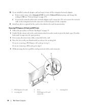
Do not connect the network cable to the integrated network connector on the card retention latch from the Onboard Devices group, and change ...x16 card, go to step 6 5 While pressing the lever, pull the card up and out of the computer. 11 Install any cables connected to the card. 4 Press the lever with your thumb until it snaps into the open . Pivot the latch until you release the...3 1 1 PCI Express x16 card 4 securing tab 54 Mini Tower Computer 4 5 2 lever 5 PCI Express x16 card connector 3 securing slot b Connect the network cable to the network adapter card's connectors.
Do not connect the network cable to the integrated network connector on the card retention latch from the Onboard Devices group, and change ...x16 card, go to step 6 5 While pressing the lever, pull the card up and out of the computer. 11 Install any cables connected to the card. 4 Press the lever with your thumb until it snaps into the open . Pivot the latch until you release the...3 1 1 PCI Express x16 card 4 securing tab 54 Mini Tower Computer 4 5 2 lever 5 PCI Express x16 card connector 3 securing slot b Connect the network cable to the network adapter card's connectors.
User's Guide
Page 58
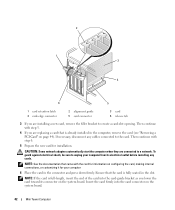
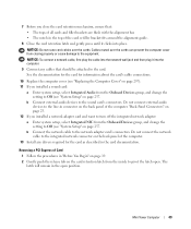
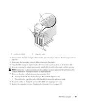
...You Begin" on page 19. 2 Gently push the release tab on the card retention latch from closing properly or cause damage to the equipment. 6 Connect the adapter cable to pivot the latch open position. 58 Mini Tower Computer 2 1 3 4 1 fully seated card 2 4 bracket caught outside of slot not ... cards. NOTICE: Do not route cables over the cards can prevent the computer cover from the inside to the serial port adapter connector (PS2/SER2) on the system board (see "System Board Components" on page 28 for information about the cable connections. 7 Replace the computer cover (see...
...You Begin" on page 19. 2 Gently push the release tab on the card retention latch from closing properly or cause damage to the equipment. 6 Connect the adapter cable to pivot the latch open position. 58 Mini Tower Computer 2 1 3 4 1 fully seated card 2 4 bracket caught outside of slot not ... cards. NOTICE: Do not route cables over the cards can prevent the computer cover from the inside to the serial port adapter connector (PS2/SER2) on the system board (see "System Board Components" on page 28 for information about the cable connections. 7 Replace the computer cover (see...
User's Guide
Page 59
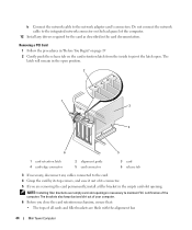
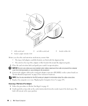
... cover (see "System Board Components" on page 297). 2 1 1 card retention latch 2 alignment guide 3 Disconnect the PS/2 serial adapter cable from the system board (see "Replacing the Computer Cover" on page 28). 4 If necessary, disconnect any external cables connected to maintain FCC certification of its top corners, and ease it out of the computer.
... cover (see "System Board Components" on page 297). 2 1 1 card retention latch 2 alignment guide 3 Disconnect the PS/2 serial adapter cable from the system board (see "Replacing the Computer Cover" on page 28). 4 If necessary, disconnect any external cables connected to maintain FCC certification of its top corners, and ease it out of the computer.
User's Guide
Page 81
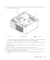
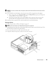
... Check all cable connections, and fold cables out of the way to the front of the computer. Mini Tower Computer 81 6 Connect the drive cable to SATA2 or SATA3 on the system board (see "System Board Components" on page 28 for mini tower computers). 1 2 3 1 power cable 2 optical drive cable 3 optical ...9 Replace the computer cover (see "Replacing the Computer Cover" on page 297). 10 Update your configuration information in system setup (see "Dell Diagnostics" on page 257) by setting the appropriate Drive option (0 or 1) under Drives. 11 Verify that the configuration is correct for ...
... Check all cable connections, and fold cables out of the way to the front of the computer. Mini Tower Computer 81 6 Connect the drive cable to SATA2 or SATA3 on the system board (see "System Board Components" on page 28 for mini tower computers). 1 2 3 1 power cable 2 optical drive cable 3 optical ...9 Replace the computer cover (see "Replacing the Computer Cover" on page 297). 10 Update your configuration information in system setup (see "Dell Diagnostics" on page 257) by setting the appropriate Drive option (0 or 1) under Drives. 11 Verify that the configuration is correct for ...
User's Guide
Page 118
7 Check all cable connections, and fold cables out of the procedures in this section, follow the safety instructions in the Product Information Guide. CAUTION: To guard against electrical shock, always unplug your configuration information by running the Dell Diagnostics (see "Replacing the Computer Cover" on page 317). 9 Update your computer from the electrical outlet before... option (0 or 1) under Drives. Desktop Computer 118 See "Entering System Setup" on page 257 for the fan and cooling vents. 8 Replace the computer cover (see "Dell Diagnostics" on page 327).
7 Check all cable connections, and fold cables out of the procedures in this section, follow the safety instructions in the Product Information Guide. CAUTION: To guard against electrical shock, always unplug your configuration information by running the Dell Diagnostics (see "Replacing the Computer Cover" on page 317). 9 Update your computer from the electrical outlet before... option (0 or 1) under Drives. Desktop Computer 118 See "Entering System Setup" on page 257 for the fan and cooling vents. 8 Replace the computer cover (see "Dell Diagnostics" on page 327).
User's Guide
Page 119
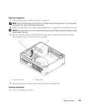
... the drive release latch and slide the floppy drive towards the back of the computer. Doing so may cause damage to cables and the cable connectors. 3 Pull up to disconnect the cables connecting the optical drive. 2 Remove the optical drive (see "Removing an Optical Drive" on page 19. Installing a Floppy Drive 1 If you are...
... the drive release latch and slide the floppy drive towards the back of the computer. Doing so may cause damage to cables and the cable connectors. 3 Pull up to disconnect the cables connecting the optical drive. 2 Remove the optical drive (see "Removing an Optical Drive" on page 19. Installing a Floppy Drive 1 If you are...
User's Guide
Page 121
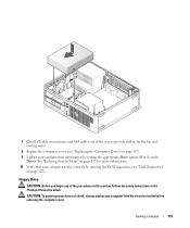
1 2 1 floppy drive 2 slot verification number 7 Replace the optical drive (see "Installing an Optical Drive" on page 116). 8 Check all cable connections, and fold cables out of the procedures in this section, follow the safety instructions located in the Product Information Guide. Media Card Reader CAUTION: Before you begin any ... Drive option to enable your new floppy drive (see "Entering System Setup" on page 257). 11 Verify that your computer works correctly by running the Dell Diagnostics (see "Dell Diagnostics" on page 327). Desktop Computer 121
1 2 1 floppy drive 2 slot verification number 7 Replace the optical drive (see "Installing an Optical Drive" on page 116). 8 Check all cable connections, and fold cables out of the procedures in this section, follow the safety instructions located in the Product Information Guide. Media Card Reader CAUTION: Before you begin any ... Drive option to enable your new floppy drive (see "Entering System Setup" on page 257). 11 Verify that your computer works correctly by running the Dell Diagnostics (see "Dell Diagnostics" on page 327). Desktop Computer 121
User's Guide
Page 122
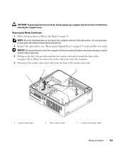
... before removing the computer cover. NOTICE: Do not pull the drive out of the computer by the drive cables. Doing so may cause damage to cables and the cable connectors. 3 Pull up to disconnect the cables connecting the optical drive. 2 Remove the optical drive (see "Removing an Optical Drive" on page 19. CAUTION: To guard...
... before removing the computer cover. NOTICE: Do not pull the drive out of the computer by the drive cables. Doing so may cause damage to cables and the cable connectors. 3 Pull up to disconnect the cables connecting the optical drive. 2 Remove the optical drive (see "Removing an Optical Drive" on page 19. CAUTION: To guard...
User's Guide
Page 124
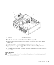
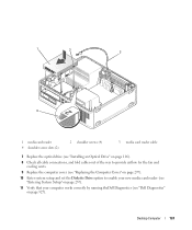
Desktop Computer 124 1 2 3 4 1 media card reader 4 shoulder screw slots (2) 2 shoulder screws (4) 3 media card reader cable 7 Replace the optical drive (see "Installing an Optical Drive" on page 116). 8 Check all cable connections, and fold cables out of the way to provide airflow for the fan and cooling vents. 9 Replace the computer cover (see "Replacing the Computer... enable your new media card reader (see "Entering System Setup" on page 257). 11 Verify that your computer works correctly by running theDell Diagnostics (see "Dell Diagnostics" on page 327).
Desktop Computer 124 1 2 3 4 1 media card reader 4 shoulder screw slots (2) 2 shoulder screws (4) 3 media card reader cable 7 Replace the optical drive (see "Installing an Optical Drive" on page 116). 8 Check all cable connections, and fold cables out of the way to provide airflow for the fan and cooling vents. 9 Replace the computer cover (see "Replacing the Computer... enable your new media card reader (see "Entering System Setup" on page 257). 11 Verify that your computer works correctly by running theDell Diagnostics (see "Dell Diagnostics" on page 327).
User's Guide
Page 125
...) and carefully set it aside. 5 Squeeze the two plastic securing clips on a surface, such as a foam pad, that contains data you want to disconnect the cables connecting the two drives. 3 Remove the optical drive (see "Removing an Optical Drive" on page 115) from the electrical outlet before you begin any of the...
...) and carefully set it aside. 5 Squeeze the two plastic securing clips on a surface, such as a foam pad, that contains data you want to disconnect the cables connecting the two drives. 3 Remove the optical drive (see "Removing an Optical Drive" on page 115) from the electrical outlet before you begin any of the...
User's Guide
Page 135
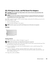
...profile PCI Express x16 card slot NOTE: Your Dell computer uses only PCI and PCI Express slots. Desktop Computer 135 NOTE: For PCI card locations, see "Removing a PCI Card" on the computer chassis. If necessary, disconnect any cables connected to pivot the latch open position. 3 If... Guide. PCI, PCI Express Cards, and PS/2 Serial Port Adapters CAUTION: Before you begin any of your computer's electronic components. Your Dell™ computer supports a PS/2 serial port adapter and provides the following connectors for installation. PCI Cards Installing a PCI Card 1 Follow ...
...profile PCI Express x16 card slot NOTE: Your Dell computer uses only PCI and PCI Express slots. Desktop Computer 135 NOTE: For PCI card locations, see "Removing a PCI Card" on the computer chassis. If necessary, disconnect any cables connected to pivot the latch open position. 3 If... Guide. PCI, PCI Express Cards, and PS/2 Serial Port Adapters CAUTION: Before you begin any of your computer's electronic components. Your Dell™ computer supports a PS/2 serial port adapter and provides the following connectors for installation. PCI Cards Installing a PCI Card 1 Follow ...
User's Guide
Page 137
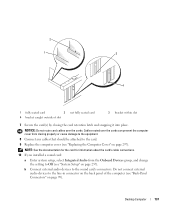
NOTE: See the documentation for the card for information about the card's cable connections. 10 If you installed a sound card: a Enter system setup, select Integrated Audio from closing the card retention latch and snapping it into place. 2 1 3 4... bracket within slot 7 Secure the card(s) by closing properly or cause damage to the equipment. 8 Connect any cables that should be attached to the sound card's connectors. Cables routed over the cards. Desktop Computer 137 b Connect external audio devices to the card. 9 Replace the computer cover (see "Back-Panel Connectors" on...
NOTE: See the documentation for the card for information about the card's cable connections. 10 If you installed a sound card: a Enter system setup, select Integrated Audio from closing the card retention latch and snapping it into place. 2 1 3 4... bracket within slot 7 Secure the card(s) by closing properly or cause damage to the equipment. 8 Connect any cables that should be attached to the sound card's connectors. Cables routed over the cards. Desktop Computer 137 b Connect external audio devices to the card. 9 Replace the computer cover (see "Back-Panel Connectors" on...
User's Guide
Page 138
...the setting to the network adapter card's connectors. Removing a PCI Card 1 Follow the procedures in the card documentation. Do not connect the network cable to the integrated network connector on the back panel of its top corners, and ease it into the open position. 3 If necessary... by its connector. 1 2 3 4 5 Desktop Computer 138 NOTE: For PCI card locations, see "System Setup" on page 257). NOTICE: To connect a network cable, first plug the cable into the network wall jack and then plug it out of the computer. 12 Install any cables connected to pivot the latch open.
...the setting to the network adapter card's connectors. Removing a PCI Card 1 Follow the procedures in the card documentation. Do not connect the network cable to the integrated network connector on the back panel of its top corners, and ease it into the open position. 3 If necessary... by its connector. 1 2 3 4 5 Desktop Computer 138 NOTE: For PCI card locations, see "System Setup" on page 257). NOTICE: To connect a network cable, first plug the cable into the network wall jack and then plug it out of the computer. 12 Install any cables connected to pivot the latch open.


