Quick Reference
Page 9
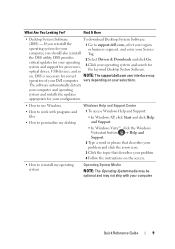
...The software automatically detects your computer and operating system and installs the updates appropriate for the keyword Desktop System Software. DSS is necessary for processors, optical drives, USB devices, and so 2 Select Drivers & Downloads and click Go. 3 Click your Service computer, you should ...3 Click the topic that describes your problem. 4 Follow the instructions on your Dell computer. DSS provides critical updates for your operating system and support for correct NOTE: The support.dell.com user interface may not ship with programs and files • How to reinstall...
...The software automatically detects your computer and operating system and installs the updates appropriate for the keyword Desktop System Software. DSS is necessary for processors, optical drives, USB devices, and so 2 Select Drivers & Downloads and click Go. 3 Click your Service computer, you should ...3 Click the topic that describes your problem. 4 Follow the instructions on your Dell computer. DSS provides critical updates for your operating system and support for correct NOTE: The support.dell.com user interface may not ship with programs and files • How to reinstall...

Quick Reference
Page 10
... its metal mounting bracket. Do not touch the components or contacts on the operating system you begin any of your computer. Hold a component such as a processor by its edges, not by its pins. 10 Quick Reference Guide NOTICE: Handle components and cards with your disc varies based on a card. NOTE: The...
... its metal mounting bracket. Do not touch the components or contacts on the operating system you begin any of your computer. Hold a component such as a processor by its edges, not by its pins. 10 Quick Reference Guide NOTICE: Handle components and cards with your disc varies based on a card. NOTE: The...
Quick Reference
Page 36
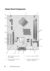
System Board Components 1 17 16 2 3 15 4 14 13 5 12 6 11 10 9 1 internal speaker connector (INT_SPKR) 3 processor power connector (12VPOWER) 8 7 2 processor connector (CPU) 4 memory module connectors (DIMM_1, DIMM_2) 36 Quick Reference Guide
System Board Components 1 17 16 2 3 15 4 14 13 5 12 6 11 10 9 1 internal speaker connector (INT_SPKR) 3 processor power connector (12VPOWER) 8 7 2 processor connector (CPU) 4 memory module connectors (DIMM_1, DIMM_2) 36 Quick Reference Guide
Quick Reference
Page 46
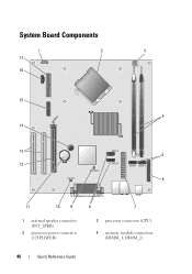
System Board Components 1 17 16 2 3 15 4 14 13 5 12 6 11 10 9 1 internal speaker connector (INT_SPKR) 3 processor power connector (12VPOWER) 8 7 2 processor connector (CPU) 4 memory module connectors (DIMM_1, DIMM_2) 46 Quick Reference Guide
System Board Components 1 17 16 2 3 15 4 14 13 5 12 6 11 10 9 1 internal speaker connector (INT_SPKR) 3 processor power connector (12VPOWER) 8 7 2 processor connector (CPU) 4 memory module connectors (DIMM_1, DIMM_2) 46 Quick Reference Guide
Quick Reference
Page 57
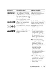
press the power button. A possible BIOS failure has occurred; the computer is in the recovery mode. A possible processor failure has Reinstall the processor and occurred. Quick Reference Guide 57 The diagnostic lights are detected, but a memory failure has occurred. • If you have one module, and then restart ... in a normal Plug the computer into a "off" condition, or a possible working memory of the same type into your computer. • If the problem persists, contact Dell. Run the BIOS Recovery utility, wait for instructions on how to the operating system.
press the power button. A possible BIOS failure has occurred; the computer is in the recovery mode. A possible processor failure has Reinstall the processor and occurred. Quick Reference Guide 57 The diagnostic lights are detected, but a memory failure has occurred. • If you have one module, and then restart ... in a normal Plug the computer into a "off" condition, or a possible working memory of the same type into your computer. • If the problem persists, contact Dell. Run the BIOS Recovery utility, wait for instructions on how to the operating system.
User's Guide
Page 9
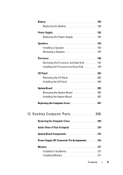
Battery 190 Replacing the Battery 190 Power Supply 192 Replacing the Power Supply 192 Speakers 194 Installing a Speaker 194 Removing a Speaker 195 Processor 196 Removing the Processor and Heat Sink 197 Installing the Processor and Heat Sink 199 I/O Panel 203 Removing the I/O Panel 203 Installing the I/O Panel 204 System Board 205 Removing the System...
Battery 190 Replacing the Battery 190 Power Supply 192 Replacing the Power Supply 192 Speakers 194 Installing a Speaker 194 Removing a Speaker 195 Processor 196 Removing the Processor and Heat Sink 197 Installing the Processor and Heat Sink 199 I/O Panel 203 Removing the I/O Panel 203 Installing the I/O Panel 204 System Board 205 Removing the System...

User's Guide
Page 10
... 241 Replacing the Battery 241 Power Supply 242 Replacing the Power Supply 243 Speakers 245 Installing a Speaker 245 Removing a Speaker 246 Processor 247 Removing the Processor and Heat Sink 247 Installing the Processor 249 I/O Panel 253 Removing the I/O Panel 253 Installing the I/O Panel 254 System Board 255 Removing the System Board 255 Installing...
... 241 Replacing the Battery 241 Power Supply 242 Replacing the Power Supply 243 Speakers 245 Installing a Speaker 245 Removing a Speaker 246 Processor 247 Removing the Processor and Heat Sink 247 Installing the Processor 249 I/O Panel 253 Removing the I/O Panel 253 Installing the I/O Panel 254 System Board 255 Removing the System Board 255 Installing...
User's Guide
Page 17
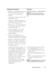
...necessary for correct operation of software and hardware updates for your operating system and support for your may vary depending on your Dell computer. Upgrade information for 1 Go to view the appropriate support site. • Upgrades - What Are You Looking For...? configuration. and operating system and installs the NOTE: The support.dell.com user interface updates appropriate for processors, optical drives, USB devices, and so on my computer configuration, product specifications, and white papers • Downloads ...
...necessary for correct operation of software and hardware updates for your operating system and support for your may vary depending on your Dell computer. Upgrade information for 1 Go to view the appropriate support site. • Upgrades - What Are You Looking For...? configuration. and operating system and installs the NOTE: The support.dell.com user interface updates appropriate for processors, optical drives, USB devices, and so on my computer configuration, product specifications, and white papers • Downloads ...
User's Guide
Page 27
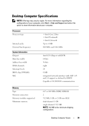
Mini Tower Computer Views 27 Processor Processor type Internal cache Front Side Bus frequency System Information Chipset Data bus width Address bus width DMA channels Interrupt levels BIOS chip (NVRAM) NIC Memory ...
Mini Tower Computer Views 27 Processor Processor type Internal cache Front Side Bus frequency System Information Chipset Data bus width Address bus width DMA channels Interrupt levels BIOS chip (NVRAM) NIC Memory ...
User's Guide
Page 39
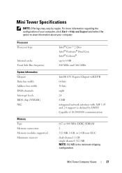
... MHz DDR2 SDRAM 2 512 MB, 1 GB, or 2 GB non-ECC dual-channel: 1 GB single-channel: 512 MB NOTE: 512 MB is the minimum shipping configuration. Processor Processor type Internal cache External bus frequency System Information Chipset Data bus width Address bus width DMA channels Interrupt levels BIOS chip (NVRAM) NIC • Intel...
... MHz DDR2 SDRAM 2 512 MB, 1 GB, or 2 GB non-ECC dual-channel: 1 GB single-channel: 512 MB NOTE: 512 MB is the minimum shipping configuration. Processor Processor type Internal cache External bus frequency System Information Chipset Data bus width Address bus width DMA channels Interrupt levels BIOS chip (NVRAM) NIC • Intel...
User's Guide
Page 66
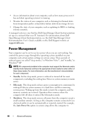
... the computer to use less power when you are restored. NOTE: All components installed in system setup. • Access information about Dell OpenManage Client Instrumentation, see the manufacturer's documentation for each component. • Standby. A managed system is one that uses IT Assistant.... However, system memory remains active. • Hibernate. For information about your computer, such as how many processors it has and what operating system it is reduced or turned off when it can be automatically or remotely started. For more information...
... the computer to use less power when you are restored. NOTE: All components installed in system setup. • Access information about Dell OpenManage Client Instrumentation, see the manufacturer's documentation for each component. • Standby. A managed system is one that uses IT Assistant.... However, system memory remains active. • Hibernate. For information about your computer, such as how many processors it has and what operating system it is reduced or turned off when it can be automatically or remotely started. For more information...

User's Guide
Page 81
... Info PCI Info Date/Time Boot Sequence Identifies the Processor Type, Processor Clock Speed, Processor Bus Speed, Processor L2 Cache size, and Processor ID. Lists the Installed Memory size, Memory Speed, Memory Channel Mode (dual or single), Memory Technology, and memory slot information of these... respective Slot ID. This option enables or disables the floppy drive. The options are denoted as "Empty." System Setup 81 States whether the processor is default. NOTE: If USB is selected, ensure that the USB Controller setup option under Onboard Devices is set to boot from the sequence...
... Info PCI Info Date/Time Boot Sequence Identifies the Processor Type, Processor Clock Speed, Processor Bus Speed, Processor L2 Cache size, and Processor ID. Lists the Installed Memory size, Memory Speed, Memory Channel Mode (dual or single), Memory Technology, and memory slot information of these... respective Slot ID. This option enables or disables the floppy drive. The options are denoted as "Empty." System Setup 81 States whether the processor is default. NOTE: If USB is selected, ensure that the USB Controller setup option under Onboard Devices is set to boot from the sequence...
User's Guide
Page 84
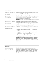
... CPU Core (On default) SpeedStep (Off default) Limit CPUID Value (Off default) HDD Acoustic Mode (Bypass default) Determines whether the processor will support. Some operating systems won't complete installation when the maximum CPUID function supported is not affected. NOTE: This option may cause the...Security Admin Password (Not Set default) Displays the current status of your hard drive image. Limits the maximum value the processor standard CPUID function will have one or two cores enabled. On enables the second core. Enables Intel® SpeedStep® for ...
... CPU Core (On default) SpeedStep (Off default) Limit CPUID Value (Off default) HDD Acoustic Mode (Bypass default) Determines whether the processor will support. Some operating systems won't complete installation when the maximum CPUID function supported is not affected. NOTE: This option may cause the...Security Admin Password (Not Set default) Displays the current status of your hard drive image. Limits the maximum value the processor standard CPUID function will have one or two cores enabled. On enables the second core. Enables Intel® SpeedStep® for ...

User's Guide
Page 104
... connections (see "Contacting Dell" on page 267 for assistance). H A R D - Possible hard disk drive failure during HDD POST. C P U F A N F A I C A L S U P P O R T - Replace the CPU fan (see "Removing the Processor and Heat Sink" on... be defective or a cable may not match the hardware configuration. D I S K D R I V E F A I L U R E - Check cables /swap hard disks (see "Contacting Dell" on page 267 for assistance). Replace battery (see "Replacing the Battery" on page 190 or see "Contacting Dell" on page 197). D I S K E T T E R E A D F A I L U R E - D I S K E T T E D R I V E 0 ...
... connections (see "Contacting Dell" on page 267 for assistance). H A R D - Possible hard disk drive failure during HDD POST. C P U F A N F A I C A L S U P P O R T - Replace the CPU fan (see "Removing the Processor and Heat Sink" on... be defective or a cable may not match the hardware configuration. D I S K D R I V E F A I L U R E - Check cables /swap hard disks (see "Contacting Dell" on page 267 for assistance). Replace battery (see "Replacing the Battery" on page 190 or see "Contacting Dell" on page 197). D I S K E T T E R E A D F A I L U R E - D I S K E T T E D R I V E 0 ...
User's Guide
Page 106
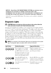
DELL RECOMMENDS THAT YOU BACK UP YOUR DATA REGULARLY. Diagnostic Lights CAUTION: Before you troubleshoot a problem, your computer has four lights labeled "1," "2," "3," and "4" on the lights .... The lights can appear either vertical or horizontal. The diagnostic lights are not lit after the computer successfully boots to the operating system. NOTICE - A possible processor failure has Reinstall the processor and occurred. HARD DRIVE SELF MONITORING SYSTEM HAS REPORTED THAT A PARAMETER HAS EXCEEDED ITS NORMAL OPERATING RANGE.
DELL RECOMMENDS THAT YOU BACK UP YOUR DATA REGULARLY. Diagnostic Lights CAUTION: Before you troubleshoot a problem, your computer has four lights labeled "1," "2," "3," and "4" on the lights .... The lights can appear either vertical or horizontal. The diagnostic lights are not lit after the computer successfully boots to the operating system. NOTICE - A possible processor failure has Reinstall the processor and occurred. HARD DRIVE SELF MONITORING SYSTEM HAS REPORTED THAT A PARAMETER HAS EXCEEDED ITS NORMAL OPERATING RANGE.

User's Guide
Page 125
... Components" on page 150). The computer is receiving electrical power, but an internal power problem may be malfunctioning or incorrectly installed. • Ensure that the processor power cable is set to match the AC power at your printer, contact the printer's manufacturer. C H E C K T H E P R I N T E R D O C U M E N T A T I S S T E A D Y A M B E R - E L I M I N A T E I N G A M B E R - See the printer documentation for your location (if applicable...
... Components" on page 150). The computer is receiving electrical power, but an internal power problem may be malfunctioning or incorrectly installed. • Ensure that the processor power cable is set to match the AC power at your printer, contact the printer's manufacturer. C H E C K T H E P R I N T E R D O C U M E N T A T I S S T E A D Y A M B E R - E L I M I N A T E I N G A M B E R - See the printer documentation for your location (if applicable...
User's Guide
Page 131
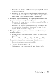
- Ensure that the electrical outlet is steady amber, a device may be malfunctioning or incorrectly installed. - Ensure that the processor power cable is securely connected to the system board (see "Cards" on page 157). • Eliminate interference. Too many devices on page 212). • If ...
- Ensure that the electrical outlet is steady amber, a device may be malfunctioning or incorrectly installed. - Ensure that the processor power cable is securely connected to the system board (see "Cards" on page 157). • Eliminate interference. Too many devices on page 212). • If ...
User's Guide
Page 144
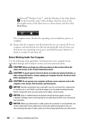
... to ensure your computer from the electrical outlet before you are turned off . NOTICE: When you begin any covers removed, such as a processor by its edges, not by Dell is complete. 2 Ensure that the computer and all attached devices are disconnecting this section, follow the safety instructions in the Product Information Guide...
... to ensure your computer from the electrical outlet before you are turned off . NOTICE: When you begin any covers removed, such as a processor by its edges, not by Dell is complete. 2 Ensure that the computer and all attached devices are disconnecting this section, follow the safety instructions in the Product Information Guide...

User's Guide
Page 196
... of your computer, discharge static electricity from the chassis of the procedures in this section, follow the safety instructions located in the Product Information Guide. Processor CAUTION: Before you touch any of the computer. 5 Replace the computer cover. 6 Turn on the computer chassis. 196 Mini Tower Computer Parts
... of your computer, discharge static electricity from the chassis of the procedures in this section, follow the safety instructions located in the Product Information Guide. Processor CAUTION: Before you touch any of the computer. 5 Replace the computer cover. 6 Turn on the computer chassis. 196 Mini Tower Computer Parts

User's Guide
Page 197
Do not use excessive force to separate the heat sink assembly from the processor to avoid damaging the processor. 6 Rotate the heat sink assembly upward gently, and remove it . Lay the heat sink assembly down on the opposite side. Be sure that are routed ... from the bracket projection. 5 Release the clamp grip from the computer. NOTICE: A strong thermal grease bond may become very hot during normal operation. Removing the Processor and Heat Sink 1 Follow the procedures in "Before You Begin" on page 143. 2 Remove the computer cover (see "Removing the Computer Cover" on page 147...
Do not use excessive force to separate the heat sink assembly from the processor to avoid damaging the processor. 6 Rotate the heat sink assembly upward gently, and remove it . Lay the heat sink assembly down on the opposite side. Be sure that are routed ... from the bracket projection. 5 Release the clamp grip from the computer. NOTICE: A strong thermal grease bond may become very hot during normal operation. Removing the Processor and Heat Sink 1 Follow the procedures in "Before You Begin" on page 143. 2 Remove the computer cover (see "Removing the Computer Cover" on page 147...


