
Quick Reference
Page 4
System Board Components 36 Replacing the Computer Cover 37 Mini Tower Computer 38 Front View 38 Back View 40 Back Panel Connectors 41 Removing the Computer Cover 43 Inside View of Your Computer 45 System Board Components 46 Replacing the Computer Cover 47 Solving Problems 47 Dell Diagnostics 48 Power Lights 51 Beep Codes 53 System Messages 54 Diagnostic Lights 56 Clearing Forgotten Passwords 60 Clearing CMOS Settings 62 Flashing the BIOS 63 Index 65 4 Contents
System Board Components 36 Replacing the Computer Cover 37 Mini Tower Computer 38 Front View 38 Back View 40 Back Panel Connectors 41 Removing the Computer Cover 43 Inside View of Your Computer 45 System Board Components 46 Replacing the Computer Cover 47 Solving Problems 47 Dell Diagnostics 48 Power Lights 51 Beep Codes 53 System Messages 54 Diagnostic Lights 56 Clearing Forgotten Passwords 60 Clearing CMOS Settings 62 Flashing the BIOS 63 Index 65 4 Contents

Quick Reference
Page 38
Use the optical drive to identify your computer when you access the Dell Support website or call Support. Mini Tower Computer Front View 1 2 3 10 9 4 8 5 6 7 1 Service Tag 2 optical drive Use the Service Tag to play a CD/DVD. 38 Quick Reference Guide
Use the optical drive to identify your computer when you access the Dell Support website or call Support. Mini Tower Computer Front View 1 2 3 10 9 4 8 5 6 7 1 Service Tag 2 optical drive Use the Service Tag to play a CD/DVD. 38 Quick Reference Guide
User's Guide
Page 3
Contents 1 Finding Information 13 2 Mini Tower Computer Views 21 Front View 21 Back View 23 Back Panel Connectors 24 Mini Tower Specifications 27 3 Desktop Computer Views 33 Front View 33 Back View 35 Back Panel Connectors 36 Desktop Computer Specifications 39 4 Setting Up Your Computer 47 Installing Your Computer in an Enclosure 47 Setting Up a Home and Office Network 49 Connecting to a Network Adapter 49 Network Setup 50 Contents 3
Contents 1 Finding Information 13 2 Mini Tower Computer Views 21 Front View 21 Back View 23 Back Panel Connectors 24 Mini Tower Specifications 27 3 Desktop Computer Views 33 Front View 33 Back View 35 Back Panel Connectors 36 Desktop Computer Specifications 39 4 Setting Up Your Computer 47 Installing Your Computer in an Enclosure 47 Setting Up a Home and Office Network 49 Connecting to a Network Adapter 49 Network Setup 50 Contents 3

User's Guide
Page 8
Turning Off Your Computer 143 Before Working Inside Your Computer 144 12 Mini Tower Computer Parts 147 Removing the Computer Cover 147 Inside View of Your Computer 149 System Board Components 150 Power Supply DC Connector Pin Assignments . . . . . 152 ...
Turning Off Your Computer 143 Before Working Inside Your Computer 144 12 Mini Tower Computer Parts 147 Removing the Computer Cover 147 Inside View of Your Computer 149 System Board Components 150 Power Supply DC Connector Pin Assignments . . . . . 152 ...

User's Guide
Page 22
... Tag to identify your computer when you access the Dell Support website or call Support. 2 optical drive Use the optical drive to play a CD/DVD. 3 floppy drive The floppy drive is optional. 4 drive activity light The drive activity light is established. 22 Mini Tower Computer Views For more information on booting to a USB...
... Tag to identify your computer when you access the Dell Support website or call Support. 2 optical drive Use the optical drive to play a CD/DVD. 3 floppy drive The floppy drive is optional. 4 drive activity light The drive activity light is established. 22 Mini Tower Computer Views For more information on booting to a USB...

User's Guide
Page 24
Blocking them would cause serious thermal problems. Back Panel Connectors 1 2 34 9 8 5 6 7 24 Mini Tower Computer Views CAUTION: Ensure that none of the computer. 1 cover release latch This latch allows you to secure the computer cover to the chassis with a ...
Blocking them would cause serious thermal problems. Back Panel Connectors 1 2 34 9 8 5 6 7 24 Mini Tower Computer Views CAUTION: Ensure that none of the computer. 1 cover release latch This latch allows you to secure the computer cover to the chassis with a ...
User's Guide
Page 25
... configured to ensure reliable operation. 4 network activity light This light flashes yellow when the computer is recommended that the network cable has been securely attached. Mini Tower Computer Views 25 A click indicates that you use the connector on " state. 5 line-out connector Use the green line-out connector to either a network jack...
... configured to ensure reliable operation. 4 network activity light This light flashes yellow when the computer is recommended that the network cable has been securely attached. Mini Tower Computer Views 25 A click indicates that you use the connector on " state. 5 line-out connector Use the green line-out connector to either a network jack...

User's Guide
Page 26
... that you connect occasionally, such as joysticks or cameras. 8 VGA video connector Connect the monitor's VGA cable to the VGA connector on page 80. 26 Mini Tower Computer Views 6 microphone/line-
... that you connect occasionally, such as joysticks or cameras. 8 VGA video connector Connect the monitor's VGA cable to the VGA connector on page 80. 26 Mini Tower Computer Views 6 microphone/line-
User's Guide
Page 27
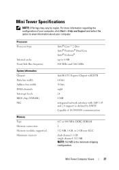
Mini Tower Specifications NOTE: Offerings may vary by DMTF Capable of your computer, click Start→ Help and Support and select the option to view information about ... Intel® G31 Express Chipset w/ICH7R 64 bits 36 bits eight 24 8 MB integrated network interface with ASF 1.03 and 2.0 support as defined by region. Mini Tower Computer Views 27
Mini Tower Specifications NOTE: Offerings may vary by DMTF Capable of your computer, click Start→ Help and Support and select the option to view information about ... Intel® G31 Express Chipset w/ICH7R 64 bits 36 bits eight 24 8 MB integrated network interface with ASF 1.03 and 2.0 support as defined by region. Mini Tower Computer Views 27
User's Guide
Page 28
... for headphones and microphone four 7-pin connectors 34-pin connector 5-pin connector two 120-pin connectors one 164-pin (x16) connector 40-pin connector 28 Mini Tower Computer Views two front-panel connectors for line-in the DIMM slots. Memory (continued) Maximum memory BIOS address Ports and Connectors External connectors: Serial Parallel...
... for headphones and microphone four 7-pin connectors 34-pin connector 5-pin connector two 120-pin connectors one 164-pin (x16) connector 40-pin connector 28 Mini Tower Computer Views two front-panel connectors for line-in the DIMM slots. Memory (continued) Maximum memory BIOS address Ports and Connectors External connectors: Serial Parallel...
User's Guide
Page 29
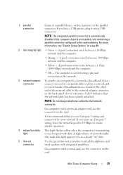
...) • green light = 10 Mbps • orange light = 100 Mbps • yellow light = 1000 Mbps (1 Gbs) Activity light (on integrated network yellow blinking light adapter) Mini Tower Computer Views 29 blinking green indicates sleep mode; solid amber indicates an internal power problem (See "Power Problems" on page 124.) hard drive access light...
...) • green light = 10 Mbps • orange light = 100 Mbps • yellow light = 1000 Mbps (1 Gbs) Activity light (on integrated network yellow blinking light adapter) Mini Tower Computer Views 29 blinking green indicates sleep mode; solid amber indicates an internal power problem (See "Power Problems" on page 124.) hard drive access light...

User's Guide
Page 30
... connectors 32 bits one x16 25 W (x16) maximum 164 pins (x16) 16 PCI Express lanes (x16) 10/100/1000 Ethernet LAN on system board 30 Mini Tower Computer Views
... connectors 32 bits one x16 25 W (x16) maximum 164 pins (x16) 16 PCI Express lanes (x16) 10/100/1000 Ethernet LAN on system board 30 Mini Tower Computer Views
User's Guide
Page 31
...° to 95°F) -40° to 65°C (-40° to 149°F) 20% to 80% (noncondensing) 5 to 350 Hz at 0.0002 G2/Hz Mini Tower Computer Views 31
...° to 95°F) -40° to 65°C (-40° to 149°F) 20% to 80% (noncondensing) 5 to 350 Hz at 0.0002 G2/Hz Mini Tower Computer Views 31

User's Guide
Page 32
Environmental (continued) Storage Maximum shock: Operating Storage Altitude: Operating Storage 5 to 500 Hz at 0.001 to 0.01 G2/Hz 40 G +/- 5% with pulse duration of 2 msec +/- 10% (equivalent to 51 cm/sec [20 in/sec]) 105 G +/- 5% with pulse duration of 2 msec +/- 10% (equivalent to 127 cm/sec [50 in/sec]) -15.2 to 3048 m (-50 to 10,000 ft) -15.2 to 10,668 m (-50 to 35,000 ft) 32 Mini Tower Computer Views
Environmental (continued) Storage Maximum shock: Operating Storage Altitude: Operating Storage 5 to 500 Hz at 0.001 to 0.01 G2/Hz 40 G +/- 5% with pulse duration of 2 msec +/- 10% (equivalent to 51 cm/sec [20 in/sec]) 105 G +/- 5% with pulse duration of 2 msec +/- 10% (equivalent to 127 cm/sec [50 in/sec]) -15.2 to 3048 m (-50 to 10,000 ft) -15.2 to 10,668 m (-50 to 35,000 ft) 32 Mini Tower Computer Views

User's Guide
Page 47
... at least 30 percent airflow through the enclosure (front and back). For details about your computer's specifications, see "Desktop Computer Specifications" on page 39 or "Mini Tower Specifications" on page 27. • Leave a 10.2 cm (4 in) minimum clearance on your computer's specifications, you reach your computer in an enclosure: NOTICE: The operating...
... at least 30 percent airflow through the enclosure (front and back). For details about your computer's specifications, see "Desktop Computer Specifications" on page 39 or "Mini Tower Specifications" on page 27. • Leave a 10.2 cm (4 in) minimum clearance on your computer's specifications, you reach your computer in an enclosure: NOTICE: The operating...
User's Guide
Page 82
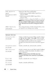
... Boot enables the controller but disables the ability to boot from a USB device. SATA Operation (RAID Autodetect/AHCI default) SMART Reporting (Off default) Options for Mini Tower and Desktop: • RAID Autodetect/AHCI (RAID if signed drives, otherwise AHCI) • RAID Autodetect/ATA (RAID if signed drives, otherwise ATA) • RAID On...
... Boot enables the controller but disables the ability to boot from a USB device. SATA Operation (RAID Autodetect/AHCI default) SMART Reporting (Off default) Options for Mini Tower and Desktop: • RAID Autodetect/AHCI (RAID if signed drives, otherwise AHCI) • RAID Autodetect/ATA (RAID if signed drives, otherwise ATA) • RAID On...

User's Guide
Page 147
Mini Tower Computer Parts Removing the Computer Cover CAUTION: Before you are not custom replacable. 1 Follow the procedures in "Before You Begin" on page 143. CAUTION: Some ... chapter may be replacable by moving fan blades, or other unexpected injuries, always unplug your computer on a level, protected surface to support the removed cover. Mini Tower Computer Parts 147 NOTE: Ensure that you begin any of the parts described in the Product Information Guide. CAUTION: To guard against electrical shock, laceration...
Mini Tower Computer Parts Removing the Computer Cover CAUTION: Before you are not custom replacable. 1 Follow the procedures in "Before You Begin" on page 143. CAUTION: Some ... chapter may be replacable by moving fan blades, or other unexpected injuries, always unplug your computer on a level, protected surface to support the removed cover. Mini Tower Computer Parts 147 NOTE: Ensure that you begin any of the parts described in the Product Information Guide. CAUTION: To guard against electrical shock, laceration...

User's Guide
Page 148
1 2 3 1 security cable slot 3 padlock ring 2 cover release latch 3 Release the computer cover by pulling it away from the front of the computer and lifting it up. 4 Set the cover aside in a secure location. 148 Mini Tower Computer Parts
1 2 3 1 security cable slot 3 padlock ring 2 cover release latch 3 Release the computer cover by pulling it away from the front of the computer and lifting it up. 4 Set the cover aside in a secure location. 148 Mini Tower Computer Parts

User's Guide
Page 153
Pin Number 1 2 3 4 5 6 7 8 9 10 11 12 13 14 15 16 17 18 19 20 21 22 23 24 Signal name 3.3 V 3.3 V RTN 5 V RTN 5 V RTN POK 5 V AUX +12 V +12 V 3.3 V 3.3 V -12 V RTN PS_ON RTN RTN RTN OPEN 5 V 5 V 5 V RTN Wire Color Orange Orange Black Red Black Red Black Gray Purple Yellow Yellow Orange Orange Blue Black Green Black Black Black Wire Size 20 AWG 20 AWG 20 AWG 20 AWG 20 AWG 20 AWG 20 AWG 22 AWG 20 AWG 20 AWG 20 AWG 20 AWG 20 AWG 22 AWG 20 AWG 22 AWG 20 AWG 20 AWG 20 AWG Red Red Red Black 20 AWG 20 AWG 20 AWG 20 AWG Mini Tower Computer Parts 153
Pin Number 1 2 3 4 5 6 7 8 9 10 11 12 13 14 15 16 17 18 19 20 21 22 23 24 Signal name 3.3 V 3.3 V RTN 5 V RTN 5 V RTN POK 5 V AUX +12 V +12 V 3.3 V 3.3 V -12 V RTN PS_ON RTN RTN RTN OPEN 5 V 5 V 5 V RTN Wire Color Orange Orange Black Red Black Red Black Gray Purple Yellow Yellow Orange Orange Blue Black Green Black Black Black Wire Size 20 AWG 20 AWG 20 AWG 20 AWG 20 AWG 20 AWG 20 AWG 22 AWG 20 AWG 20 AWG 20 AWG 20 AWG 20 AWG 22 AWG 20 AWG 22 AWG 20 AWG 20 AWG 20 AWG Red Red Red Black 20 AWG 20 AWG 20 AWG 20 AWG Mini Tower Computer Parts 153

User's Guide
Page 154
DC Power Connector P2 3 4 1 2 Pin Number 1 2 3 4 Signal Name GND GND +12 VADC +12 VADC 18-AWG Wire Black Black Yellow Yellow DC Power Connectors P3, P5, P8, and P9 Pin Number 1 2 3 4 5 Signal name +3.3 VDC GND +5 VDC GND +12 VBDC DC Power Connector P7 18-AWG Wire Orange Black Red Black White 154 Mini Tower Computer Parts
DC Power Connector P2 3 4 1 2 Pin Number 1 2 3 4 Signal Name GND GND +12 VADC +12 VADC 18-AWG Wire Black Black Yellow Yellow DC Power Connectors P3, P5, P8, and P9 Pin Number 1 2 3 4 5 Signal name +3.3 VDC GND +5 VDC GND +12 VBDC DC Power Connector P7 18-AWG Wire Orange Black Red Black White 154 Mini Tower Computer Parts


