Quick Reference
Page 3
Contents Finding Information 5 Before You Begin 10 Before Working Inside Your Computer 10 Adding and Replacing Parts 11 Setting Up Your Computer 13 Installing Your Computer in an Enclosure . . . . . 13 Setting Up a Home and Office Network 15 Connecting to a Network Adapter 15 ...
Contents Finding Information 5 Before You Begin 10 Before Working Inside Your Computer 10 Adding and Replacing Parts 11 Setting Up Your Computer 13 Installing Your Computer in an Enclosure . . . . . 13 Setting Up a Home and Office Network 15 Connecting to a Network Adapter 15 ...
Quick Reference
Page 6
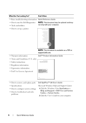
...information • End User License Agreement • How to remove and replace parts • Specifications • How to configure system settings • How to troubleshoot and solve problems Dell OptiPlex™ 330 User's Guide Microsoft Windows Help and Support Center 1 Click the Windows Vista ...Start button→ Help and Support→ Dell User and System Guides→ System Guides. 2 Click the User...
...information • End User License Agreement • How to remove and replace parts • Specifications • How to configure system settings • How to troubleshoot and solve problems Dell OptiPlex™ 330 User's Guide Microsoft Windows Help and Support Center 1 Click the Windows Vista ...Start button→ Help and Support→ Dell User and System Guides→ System Guides. 2 Click the User...
Quick Reference
Page 11
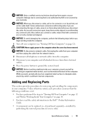
...pull on its connector or on its pull-tab, not on the locking tabs before you connect a cable, ensure that is not authorized by Dell is not covered by touching an unpainted metal surface, such as the metal at the back of cable, press in reverse order. if you ...then unplug the cable from the network device. 2 Disconnect all telephone or network cables from the computer. 3 Disconnect your computer. Adding and Replacing Parts This section provides procedures for removing and installing the components in "Turning Off Your Computer" on page 12 and "Before Working Inside Your Computer" ...
...pull on its connector or on its pull-tab, not on the locking tabs before you connect a cable, ensure that is not authorized by Dell is not covered by touching an unpainted metal surface, such as the metal at the back of cable, press in reverse order. if you ...then unplug the cable from the network device. 2 Disconnect all telephone or network cables from the computer. 3 Disconnect your computer. Adding and Replacing Parts This section provides procedures for removing and installing the components in "Turning Off Your Computer" on page 12 and "Before Working Inside Your Computer" ...

Quick Reference
Page 37
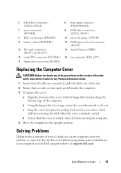
Quick Reference Guide 37 b Using the hinge tabs as leverage, rotate the cover downward to close it. d Ensure that no tools or extra parts are left inside the computer. 3 To replace the cover: a Align the bottom of the cover with the hinge tabs located along the bottom edge of ...
Quick Reference Guide 37 b Using the hinge tabs as leverage, rotate the cover downward to close it. d Ensure that no tools or extra parts are left inside the computer. 3 To replace the cover: a Align the bottom of the cover with the hinge tabs located along the bottom edge of ...
Quick Reference
Page 47
d Ensure that no tools or extra parts are connected, and fold cables out of the computer. Quick Reference Guide 47 5 SATA drive connectors (SATA0, SATA1) 7 power connector (POWER) 9 RTC reset jumper (RTCRST) ... (SLOT1) 14 internal buzzer (SPKR) 16 fan connector (FAN_CPU) Replacing the Computer Cover CAUTION: Before you if your computer, see the Dell support website at support.dell.com. Solving Problems Dell provides a number of tools to help you begin any of the procedures in this section, follow the safety instructions located in the...
d Ensure that no tools or extra parts are connected, and fold cables out of the computer. Quick Reference Guide 47 5 SATA drive connectors (SATA0, SATA1) 7 power connector (POWER) 9 RTC reset jumper (RTCRST) ... (SLOT1) 14 internal buzzer (SPKR) 16 fan connector (FAN_CPU) Replacing the Computer Cover CAUTION: Before you if your computer, see the Dell support website at support.dell.com. Solving Problems Dell provides a number of tools to help you begin any of the procedures in this section, follow the safety instructions located in the...

Quick Reference
Page 65
...codes, 53 components inside, 35, 45 inside view, 35, 45 cover removing, 33, 43 replacing, 37, 47 D Dell Diagnostics, 48 Dell support site, 8 diagnostics beep codes, 53 Dell, 48 documentation End User License Agreement, 6 ergonomics, 6 online, 8 Product Information Guide, 6 Quick Reference, 6 regulatory,... warranty, 6 E End User License Agreement, 6 ergonomics information, 6 error messages beep codes, 53 H hardware beep codes, 53 Dell Diagnostics, 48 Help and Support Center, 9 help file Windows Help and Support Center, 9 I installing parts before you begin, 11 recommended tools, 12 Index 65
...codes, 53 components inside, 35, 45 inside view, 35, 45 cover removing, 33, 43 replacing, 37, 47 D Dell Diagnostics, 48 Dell support site, 8 diagnostics beep codes, 53 Dell, 48 documentation End User License Agreement, 6 ergonomics, 6 online, 8 Product Information Guide, 6 Quick Reference, 6 regulatory,... warranty, 6 E End User License Agreement, 6 ergonomics information, 6 error messages beep codes, 53 H hardware beep codes, 53 Dell Diagnostics, 48 Help and Support Center, 9 help file Windows Help and Support Center, 9 I installing parts before you begin, 11 recommended tools, 12 Index 65

User's Guide
Page 7
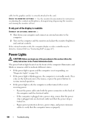
... 124 Power Problems 124 Printer Problems 125 Scanner Problems 126 Sound and Speaker Problems 127 Video and Monitor Problems 128 If only part of the display is readable 130 Power Lights 130 10 Reinstalling Software 133 Drivers 133 What Is a Driver 133 Identifying Drivers... and Hardware Problems . . 136 Restoring Your Operating System 137 Using Microsoft Windows System Restore . . . . 137 Using Dell™ PC Restore and Dell Factory Image Restore 139 Using the Operating System Media 142 11 Adding and Replacing Parts 143 Before You Begin 143 Recommended Tools 143 Contents 7
... 124 Power Problems 124 Printer Problems 125 Scanner Problems 126 Sound and Speaker Problems 127 Video and Monitor Problems 128 If only part of the display is readable 130 Power Lights 130 10 Reinstalling Software 133 Drivers 133 What Is a Driver 133 Identifying Drivers... and Hardware Problems . . 136 Restoring Your Operating System 137 Using Microsoft Windows System Restore . . . . 137 Using Dell™ PC Restore and Dell Factory Image Restore 139 Using the Operating System Media 142 11 Adding and Replacing Parts 143 Before You Begin 143 Recommended Tools 143 Contents 7

User's Guide
Page 8
Turning Off Your Computer 143 Before Working Inside Your Computer 144 12 Mini Tower Computer Parts 147 Removing the Computer Cover 147 Inside View of Your Computer 149 System Board Components 150 Power Supply DC Connector Pin Assignments . . . . . 152 Memory 155 ...
Turning Off Your Computer 143 Before Working Inside Your Computer 144 12 Mini Tower Computer Parts 147 Removing the Computer Cover 147 Inside View of Your Computer 149 System Board Components 150 Power Supply DC Connector Pin Assignments . . . . . 152 Memory 155 ...
User's Guide
Page 9
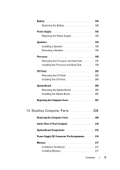
... Installing the I/O Panel 204 System Board 205 Removing the System Board 205 Installing the System Board 207 Replacing the Computer Cover 207 13 Desktop Computer Parts 209 Removing the Computer Cover 209 Inside View of Your Computer 210 System Board Components 212 Power Supply DC Connector Pin Assignments . . . . . 214 Memory 217...
... Installing the I/O Panel 204 System Board 205 Removing the System Board 205 Installing the System Board 207 Replacing the Computer Cover 207 13 Desktop Computer Parts 209 Removing the Computer Cover 209 Inside View of Your Computer 210 System Board Components 212 Power Supply DC Connector Pin Assignments . . . . . 214 Memory 217...
User's Guide
Page 15
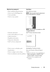
... Information Guide • How to remove and replace parts Dell OptiPlex™ 330 User's Guide • Specifications Microsoft Windows Help and Support...What Are You Looking For? • Basic troubleshooting information • How to run the Dell Diagnostics • Tools and utilities • How to troubleshoot and solve problems 1 Click the Windows Vista... start button→ Help and Support→ Dell User and System Guides→ System Guides. 2 Click the User's Guide for your computer. • Warranty...
... Information Guide • How to remove and replace parts Dell OptiPlex™ 330 User's Guide • Specifications Microsoft Windows Help and Support...What Are You Looking For? • Basic troubleshooting information • How to run the Dell Diagnostics • Tools and utilities • How to troubleshoot and solve problems 1 Click the Windows Vista... start button→ Help and Support→ Dell User and System Guides→ System Guides. 2 Click the User's Guide for your computer. • Warranty...
User's Guide
Page 115
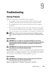
... not apply if you set your computer: • If you added or removed a part before the problem started, review the installation procedures and ensure that the part is correctly installed. • If a peripheral device does not work properly, contact Dell (see "Replacing the Battery" on page 267). If you have to the manufacturer...
... not apply if you set your computer: • If you added or removed a part before the problem started, review the installation procedures and ensure that the part is correctly installed. • If a peripheral device does not work properly, contact Dell (see "Replacing the Battery" on page 267). If you have to the manufacturer...
User's Guide
Page 130
If only part of the display is readable CONNECT AN EXTERNAL MONITOR - 1 Shut down your computer and connect an external monitor to indicate different states: • If the power light is green and the computer is not responding, see "Contacting Dell" on page 267). The power button light located on...and blinks or remains solid to the computer. 2 Turn on the computer and the monitor and adjust the monitor brightness and contrast controls. Contact Dell (see "Diagnostic Lights" on page 106. • If the power light is blinking green, the computer is plugged into both the power connector...
If only part of the display is readable CONNECT AN EXTERNAL MONITOR - 1 Shut down your computer and connect an external monitor to indicate different states: • If the power light is green and the computer is not responding, see "Contacting Dell" on page 267). The power button light located on...and blinks or remains solid to the computer. 2 Turn on the computer and the monitor and adjust the monitor brightness and contrast controls. Contact Dell (see "Diagnostic Lights" on page 106. • If the power light is blinking green, the computer is plugged into both the power connector...
User's Guide
Page 143
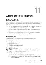
... Off Your Computer" on page 143 and "Before Working Inside Your Computer" on page 144. • You have read the safety information in the Dell™ Product Information Guide. • A component can be replaced or-if purchased separately-installed by performing the removal procedure in your computer. 1 Shut... losing data, save and close all open files and exit all open programs before you turn off your computer. Adding and Replacing Parts 143 Adding and Replacing Parts Before You Begin This section provides procedures for removing and installing the components in reverse order.
... Off Your Computer" on page 143 and "Before Working Inside Your Computer" on page 144. • You have read the safety information in the Dell™ Product Information Guide. • A component can be replaced or-if purchased separately-installed by performing the removal procedure in your computer. 1 Shut... losing data, save and close all open files and exit all open programs before you turn off your computer. Adding and Replacing Parts 143 Adding and Replacing Parts Before You Begin This section provides procedures for removing and installing the components in reverse order.
User's Guide
Page 144
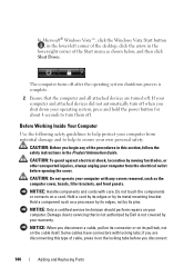
The computer turns off after the operating system shutdown process is complete. 2 Ensure that is not authorized by Dell is not covered by its pull-tab, not on the cable itself. Hold a card by its edges or by your warranty. NOTICE: Only a certified service ... system, press and hold the power button for about 4 seconds to ensure your computer from the electrical outlet before you disconnect 144 Adding and Replacing Parts Do not touch the components or contacts on your computer and attached devices did not automatically turn them off . if you are turned off . If...
The computer turns off after the operating system shutdown process is complete. 2 Ensure that is not authorized by Dell is not covered by its pull-tab, not on the cable itself. Hold a card by its edges or by your warranty. NOTICE: Only a certified service ... system, press and hold the power button for about 4 seconds to ensure your computer from the electrical outlet before you disconnect 144 Adding and Replacing Parts Do not touch the components or contacts on your computer and attached devices did not automatically turn them off . if you are turned off . If...

User's Guide
Page 145
Adding and Replacing Parts 145 As you work, periodically touch an unpainted metal surface to avoid bending any connector pins. Also, before you connect a cable, ensure that both connectors ...
Adding and Replacing Parts 145 As you work, periodically touch an unpainted metal surface to avoid bending any connector pins. Also, before you connect a cable, ensure that both connectors ...

User's Guide
Page 147
...it is resting. 2 Lay your computer from the electrical outlet before removing the cover. NOTE: Ensure that you begin any of the parts described in this section, follow the safety instructions in "Before You Begin" on its side with the computer cover facing up. Mini Tower ...Computer Parts 147 CAUTION: To guard against electrical shock, laceration by a certified service technician only and are working on a level, protected surface to support...
...it is resting. 2 Lay your computer from the electrical outlet before removing the cover. NOTE: Ensure that you begin any of the parts described in this section, follow the safety instructions in "Before You Begin" on its side with the computer cover facing up. Mini Tower ...Computer Parts 147 CAUTION: To guard against electrical shock, laceration by a certified service technician only and are working on a level, protected surface to support...

User's Guide
Page 148
1 2 3 1 security cable slot 3 padlock ring 2 cover release latch 3 Release the computer cover by pulling it away from the front of the computer and lifting it up. 4 Set the cover aside in a secure location. 148 Mini Tower Computer Parts
1 2 3 1 security cable slot 3 padlock ring 2 cover release latch 3 Release the computer cover by pulling it away from the front of the computer and lifting it up. 4 Set the cover aside in a secure location. 148 Mini Tower Computer Parts

User's Guide
Page 153
Pin Number 1 2 3 4 5 6 7 8 9 10 11 12 13 14 15 16 17 18 19 20 21 22 23 24 Signal name 3.3 V 3.3 V RTN 5 V RTN 5 V RTN POK 5 V AUX +12 V +12 V 3.3 V 3.3 V -12 V RTN PS_ON RTN RTN RTN OPEN 5 V 5 V 5 V RTN Wire Color Orange Orange Black Red Black Red Black Gray Purple Yellow Yellow Orange Orange Blue Black Green Black Black Black Wire Size 20 AWG 20 AWG 20 AWG 20 AWG 20 AWG 20 AWG 20 AWG 22 AWG 20 AWG 20 AWG 20 AWG 20 AWG 20 AWG 22 AWG 20 AWG 22 AWG 20 AWG 20 AWG 20 AWG Red Red Red Black 20 AWG 20 AWG 20 AWG 20 AWG Mini Tower Computer Parts 153
Pin Number 1 2 3 4 5 6 7 8 9 10 11 12 13 14 15 16 17 18 19 20 21 22 23 24 Signal name 3.3 V 3.3 V RTN 5 V RTN 5 V RTN POK 5 V AUX +12 V +12 V 3.3 V 3.3 V -12 V RTN PS_ON RTN RTN RTN OPEN 5 V 5 V 5 V RTN Wire Color Orange Orange Black Red Black Red Black Gray Purple Yellow Yellow Orange Orange Blue Black Green Black Black Black Wire Size 20 AWG 20 AWG 20 AWG 20 AWG 20 AWG 20 AWG 20 AWG 22 AWG 20 AWG 20 AWG 20 AWG 20 AWG 20 AWG 22 AWG 20 AWG 22 AWG 20 AWG 20 AWG 20 AWG Red Red Red Black 20 AWG 20 AWG 20 AWG 20 AWG Mini Tower Computer Parts 153

User's Guide
Page 154
DC Power Connector P2 3 4 1 2 Pin Number 1 2 3 4 Signal Name GND GND +12 VADC +12 VADC 18-AWG Wire Black Black Yellow Yellow DC Power Connectors P3, P5, P8, and P9 Pin Number 1 2 3 4 5 Signal name +3.3 VDC GND +5 VDC GND +12 VBDC DC Power Connector P7 18-AWG Wire Orange Black Red Black White 154 Mini Tower Computer Parts
DC Power Connector P2 3 4 1 2 Pin Number 1 2 3 4 Signal Name GND GND +12 VADC +12 VADC 18-AWG Wire Black Black Yellow Yellow DC Power Connectors P3, P5, P8, and P9 Pin Number 1 2 3 4 5 Signal name +3.3 VDC GND +5 VDC GND +12 VBDC DC Power Connector P7 18-AWG Wire Orange Black Red Black White 154 Mini Tower Computer Parts

User's Guide
Page 155
Mini Tower Computer Parts 155 "Mini Tower Specifications" on page 39 NOTICE: Do not install ECC or buffered memory modules. If the memory modules are not installed in matched ...
Mini Tower Computer Parts 155 "Mini Tower Specifications" on page 39 NOTICE: Do not install ECC or buffered memory modules. If the memory modules are not installed in matched ...

