Quick Reference
Page 8
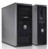
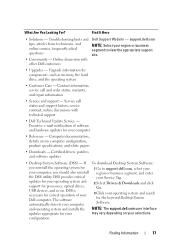
Online discussion with technical support • Dell Technical Update Service - asked questions • Community - Upgrade information for your region or business segment and online courses, frequently to view the appropriate support site. Proactive e-mail notification of software and hardware updates for components, such as memory, the hard drive, and the operating system • Customer...
Online discussion with technical support • Dell Technical Update Service - asked questions • Community - Upgrade information for your region or business segment and online courses, frequently to view the appropriate support site. Proactive e-mail notification of software and hardware updates for components, such as memory, the hard drive, and the operating system • Customer...
Quick Reference
Page 27
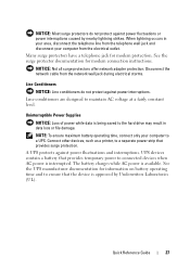
... of power while data is being saved to connected devices when AC power is interrupted. UPS devices contain a battery that provides temporary power to the hard drive may result in your area, disconnect the telephone line from the telephone wall jack and disconnect your computer to ensure that provides surge protection. The...
... of power while data is being saved to connected devices when AC power is interrupted. UPS devices contain a battery that provides temporary power to the hard drive may result in your area, disconnect the telephone line from the telephone wall jack and disconnect your computer to ensure that provides surge protection. The...
Quick Reference
Page 28
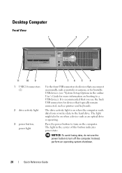
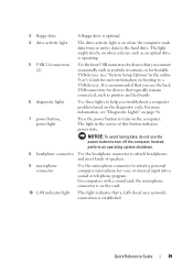
... operating system shutdown. 28 Quick Reference Guide The light might also be on when a device such as an optical drive is recommended that you connect occasionally, such as printers and keyboards. The drive activity light is on the computer. NOTICE: To avoid losing data, do not use the back USB connectors for... light 3 power button, power light 8 76 5 4 Use the front USB connectors for devices that you use the power button to the hard drive. The light in the online User's Guide for more information on booting to turn on when the computer reads data from or writes data to ...
... operating system shutdown. 28 Quick Reference Guide The light might also be on when a device such as an optical drive is recommended that you connect occasionally, such as printers and keyboards. The drive activity light is on the computer. NOTICE: To avoid losing data, do not use the back USB connectors for... light 3 power button, power light 8 76 5 4 Use the front USB connectors for devices that you use the power button to the hard drive. The light in the online User's Guide for more information on booting to turn on when the computer reads data from or writes data to ...

Quick Reference
Page 35
... the electrical outlet before removing the computer cover. CAUTION: To avoid electrical shock, always unplug your computer from the system board. 2 1 3 4 6 5 1 drives bay 2 power supply (CD/DVD, floppy, and hard drive) 3 system board 4 card slots 5 heat sink assembly 6 front I/O panel Quick Reference Guide 35 NOTICE: Be careful when opening the computer cover to...
... the electrical outlet before removing the computer cover. CAUTION: To avoid electrical shock, always unplug your computer from the system board. 2 1 3 4 6 5 1 drives bay 2 power supply (CD/DVD, floppy, and hard drive) 3 system board 4 card slots 5 heat sink assembly 6 front I/O panel Quick Reference Guide 35 NOTICE: Be careful when opening the computer cover to...
Quick Reference
Page 39
...code. Quick Reference Guide 39 It is on when the computer reads data from or writes data to the hard drive. 3 floppy drive A floppy drive is optional. 4 drive activity light The drive activity light is recommended that you use the power button to turn on the computer. The light might ...network) connection is operating. 5 USB 2.0 connectors (2) Use the front USB connectors for devices that you connect occasionally, such as an optical drive is established. Instead, perform an operating system shutdown. 8 headphone connector Use the headphone connector to a USB device).
...code. Quick Reference Guide 39 It is on when the computer reads data from or writes data to the hard drive. 3 floppy drive A floppy drive is optional. 4 drive activity light The drive activity light is recommended that you use the power button to turn on the computer. The light might ...network) connection is operating. 5 USB 2.0 connectors (2) Use the front USB connectors for devices that you connect occasionally, such as an optical drive is established. Instead, perform an operating system shutdown. 8 headphone connector Use the headphone connector to a USB device).

Quick Reference
Page 45
Inside View of Your Computer 3 2 1 1 floppy drive 3 power supply 5 heat sink assembly 6 2 optical drive 4 system board 6 hard drive 4 5 Quick Reference Guide 45
Inside View of Your Computer 3 2 1 1 floppy drive 3 power supply 5 heat sink assembly 6 2 optical drive 4 system board 6 hard drive 4 5 Quick Reference Guide 45
Quick Reference
Page 48
... the online User's Guide for technical assistance. NOTE: The Drivers and Utilities media is located on a hidden diagnostic utility partition on Dell™ computers. Starting the Dell Diagnostics From Your Hard Drive The Dell Diagnostics is optional and may not ship with your computer, perform the checks in Lockups and Software Problems (see "Finding Information...
... the online User's Guide for technical assistance. NOTE: The Drivers and Utilities media is located on a hidden diagnostic utility partition on Dell™ computers. Starting the Dell Diagnostics From Your Hard Drive The Dell Diagnostics is optional and may not ship with your computer, perform the checks in Lockups and Software Problems (see "Finding Information...
Quick Reference
Page 49
...Shut down your computer and try again. NOTE: The next steps change the boot sequence for your computer. 7 When the Dell Diagnostics Main Menu appears, select the test you see the Microsoft® Windows® desktop; On the next start-up,... the computer boots according to proceed. 6 Select Run the 32 Bit Dell Diagnostics from the boot menu and press . Select Diagnostics from the numbered list. NOTE: If you wait too long and...If multiple versions are listed, select the version appropriate for one time only. 2 Turn on your hard drive.
...Shut down your computer and try again. NOTE: The next steps change the boot sequence for your computer. 7 When the Dell Diagnostics Main Menu appears, select the test you see the Microsoft® Windows® desktop; On the next start-up,... the computer boots according to proceed. 6 Select Run the 32 Bit Dell Diagnostics from the boot menu and press . Select Diagnostics from the numbered list. NOTE: If you wait too long and...If multiple versions are listed, select the version appropriate for one time only. 2 Turn on your hard drive.
Quick Reference
Page 55
... The system cannot detect a bootable device or partition. • If the floppy drive is your boot device, ensure that the cables are connected and that a bootable floppy disk is in the drive. • If the hard drive is your boot device, ensure that the cables are connected and that the... drive is installed properly and partitioned as a boot device. • Enter system setup and ensure that...
... The system cannot detect a bootable device or partition. • If the floppy drive is your boot device, ensure that the cables are connected and that a bootable floppy disk is in the drive. • If the hard drive is your boot device, ensure that the cables are connected and that the... drive is installed properly and partitioned as a boot device. • Enter system setup and ensure that...
Quick Reference
Page 56
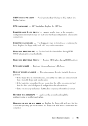
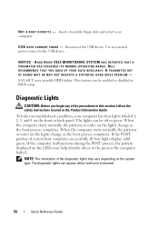
... NOT INDICATE A POTENTIAL HARD DRIVE PROBLEM - Diagnostic Lights CAUTION: Before you troubleshoot a problem, your computer. NOTICE - When the computer starts normally, the patterns or codes on the LEDs may vary depending on the system type. Disconnect the USB device. DELL RECOMMENDS THAT YOU BACK ...UP YOUR DATA REGULARLY. HARD DRIVE SELF MONITORING SYSTEM HAS REPORTED THAT A PARAMETER HAS EXCEEDED ITS NORMAL OPERATING RANGE. The lights can be...
... NOT INDICATE A POTENTIAL HARD DRIVE PROBLEM - Diagnostic Lights CAUTION: Before you troubleshoot a problem, your computer. NOTICE - When the computer starts normally, the patterns or codes on the LEDs may vary depending on the system type. Disconnect the USB device. DELL RECOMMENDS THAT YOU BACK ...UP YOUR DATA REGULARLY. HARD DRIVE SELF MONITORING SYSTEM HAS REPORTED THAT A PARAMETER HAS EXCEEDED ITS NORMAL OPERATING RANGE. The lights can be...

Quick Reference
Page 58
cables and restart the computer. A possible USB failure has occurred. A possible floppy or hard drive Reseat all USB devices, check cable connections, and then restart the computer. 58 Quick Reference Guide Reinstall all power and data failure has occurred. Light ... still exists, install a graphics card that you know works and restart the computer. • If the problem persists or the computer has integrated graphics, contact Dell.
cables and restart the computer. A possible USB failure has occurred. A possible floppy or hard drive Reseat all USB devices, check cable connections, and then restart the computer. 58 Quick Reference Guide Reinstall all power and data failure has occurred. Light ... still exists, install a graphics card that you know works and restart the computer. • If the problem persists or the computer has integrated graphics, contact Dell.
Quick Reference
Page 60
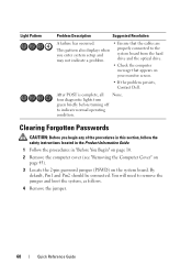
... you enter system setup and may not indicate a problem. • Ensure that the cables are properly connected to the system board from the hard drive and the optical drive. • Check the computer message that appears on the system board. four diagnostic lights turn green briefly before turning off to remove the jumper... cover (see "Removing the Computer Cover" on page 43). 3 Locate the 2-pin password jumper (PSWD) on your monitor screen. • If the problem persists, Contact Dell. You will need to indicate normal operating condition.
... you enter system setup and may not indicate a problem. • Ensure that the cables are properly connected to the system board from the hard drive and the optical drive. • Check the computer message that appears on the system board. four diagnostic lights turn green briefly before turning off to remove the jumper... cover (see "Removing the Computer Cover" on page 43). 3 Locate the 2-pin password jumper (PSWD) on your monitor screen. • If the problem persists, Contact Dell. You will need to indicate normal operating condition.
Quick Reference
Page 67
See UPS UPS User's Guide, 6 W warranty information, 6 Windows XP Index 67 S S.M.A.R.T, 56 safety instructions, 6 Service Tag, 7, 29, 38 Starting the Dell Diagnostics From the Drivers and Utilities CD, 49 Starting the Dell Diagnostics From Your Hard Drive, 48 support website, 8 system board, 36, 46 Help and Support Center, 9 Network Setup Wizard, 16 reinstalling, 9 wizards Network Setup Wizard, 16 T troubleshooting Dell Diagnostics, 48 Help and Support Center, 9 TV connect to computer, 24, 26 U uninterruptible power supply.
See UPS UPS User's Guide, 6 W warranty information, 6 Windows XP Index 67 S S.M.A.R.T, 56 safety instructions, 6 Service Tag, 7, 29, 38 Starting the Dell Diagnostics From the Drivers and Utilities CD, 49 Starting the Dell Diagnostics From Your Hard Drive, 48 support website, 8 system board, 36, 46 Help and Support Center, 9 Network Setup Wizard, 16 reinstalling, 9 wizards Network Setup Wizard, 16 T troubleshooting Dell Diagnostics, 48 Help and Support Center, 9 TV connect to computer, 24, 26 U uninterruptible power supply.

User's Guide
Page 5
... 92 Flashing the BIOS 93 About RAID Configurations 95 Verifying That RAID Is Working 95 RAID Level 1 Configuration 96 Troubleshooting RAID 96 Recovering From a Multiple Hard Drive Failure Using the Intel® RAID Option ROM Utility . . . . . 97 Contents 5
... 92 Flashing the BIOS 93 About RAID Configurations 95 Verifying That RAID Is Working 95 RAID Level 1 Configuration 96 Troubleshooting RAID 96 Recovering From a Multiple Hard Drive Failure Using the Intel® RAID Option ROM Utility . . . . . 97 Contents 5
User's Guide
Page 6
... Tools 101 Power Lights 101 Beep Codes 102 System Messages 104 Diagnostic Lights 106 Dell Diagnostics 111 When to Use the Dell Diagnostics 111 Starting the Dell Diagnostics From Your Hard Drive 111 Starting the Dell Diagnostics From the Drivers and Utilities media 112 Dell Diagnostics Main Menu 112 9 Troubleshooting 115 Solving Problems 115 Battery Problems 115...
... Tools 101 Power Lights 101 Beep Codes 102 System Messages 104 Diagnostic Lights 106 Dell Diagnostics 111 When to Use the Dell Diagnostics 111 Starting the Dell Diagnostics From Your Hard Drive 111 Starting the Dell Diagnostics From the Drivers and Utilities media 112 Dell Diagnostics Main Menu 112 9 Troubleshooting 115 Solving Problems 115 Battery Problems 115...

User's Guide
Page 8
... 156 Removing Memory 157 Cards 157 PCI and PCI Express Cards 158 Bezel 164 Removing the Bezel 165 Replacing the Bezel 166 Drives 166 Recommended Drive Cable Connections . . . . . 167 Connecting Drive Cables 167 Drive Interface Connectors 167 Connecting and Disconnecting Drive Cables . . . 168 Hard Drives 168 Installing a Second Hard Drive 174 Drive-Panel Inserts 178 Floppy Drive 180 Optical Drive 185 8 Contents
... 156 Removing Memory 157 Cards 157 PCI and PCI Express Cards 158 Bezel 164 Removing the Bezel 165 Replacing the Bezel 166 Drives 166 Recommended Drive Cable Connections . . . . . 167 Connecting Drive Cables 167 Drive Interface Connectors 167 Connecting and Disconnecting Drive Cables . . . 168 Hard Drives 168 Installing a Second Hard Drive 174 Drive-Panel Inserts 178 Floppy Drive 180 Optical Drive 185 8 Contents

User's Guide
Page 10
Removing Memory 219 Cards 219 PCI and PCI Express Cards 220 Drives 226 Recommended Drive Cable Connections . . . . . 227 Connecting Drive Cables 227 Drive Interface Connectors 228 Connecting and Disconnecting Drive Cables . . . 228 Hard Drives 229 Floppy Drive 233 Optical Drive 237 Battery 241 Replacing the Battery 241 Power Supply 242 Replacing the Power Supply 243 Speakers 245 Installing a Speaker 245...
Removing Memory 219 Cards 219 PCI and PCI Express Cards 220 Drives 226 Recommended Drive Cable Connections . . . . . 227 Connecting Drive Cables 227 Drive Interface Connectors 228 Connecting and Disconnecting Drive Cables . . . 228 Hard Drives 229 Floppy Drive 233 Optical Drive 237 Battery 241 Replacing the Battery 241 Power Supply 242 Replacing the Power Supply 243 Speakers 245 Installing a Speaker 245...
User's Guide
Page 17
... - The software automatically detects your computer 2 Select Drivers & Downloads and click Go. 3 Click your Dell computer. and operating system and installs the NOTE: The support.dell.com user interface updates appropriate for components, such as memory, the hard drive, and the operating system • Customer Care - What Are You Looking For? Service call and...
... - The software automatically detects your computer 2 Select Drivers & Downloads and click Go. 3 Click your Dell computer. and operating system and installs the NOTE: The support.dell.com user interface updates appropriate for components, such as memory, the hard drive, and the operating system • Customer Care - What Are You Looking For? Service call and...

User's Guide
Page 22
...keyboards. 6 diagnostic lights Use these lights to help you access the Dell Support website or call Support. 2 optical drive Use the optical drive to play a CD/DVD. 3 floppy drive The floppy drive is optional. 4 drive activity light The drive activity light is established. 22 Mini Tower Computer Views NOTICE: To...page 80 for devices that a LAN (local area network) connection is on when the computer reads data from or writes data to the hard drive. For more information on booting to a USB device). 1 Service Tag Use the Service Tag to identify your computer when you troubleshoot ...
...keyboards. 6 diagnostic lights Use these lights to help you access the Dell Support website or call Support. 2 optical drive Use the optical drive to play a CD/DVD. 3 floppy drive The floppy drive is optional. 4 drive activity light The drive activity light is established. 22 Mini Tower Computer Views NOTICE: To...page 80 for devices that a LAN (local area network) connection is on when the computer reads data from or writes data to the hard drive. For more information on booting to a USB device). 1 Service Tag Use the Service Tag to identify your computer when you troubleshoot ...
User's Guide
Page 29
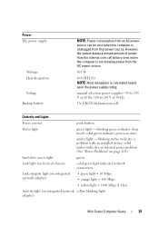
... and Lights Power control push button Power light green light - amber light - solid amber indicates an internal power problem (See "Power Problems" on page 124.) hard drive access light green Link light (on state. blinking green indicates sleep mode;
... and Lights Power control push button Power light green light - amber light - solid amber indicates an internal power problem (See "Power Problems" on page 124.) hard drive access light green Link light (on state. blinking green indicates sleep mode;


