
Quick Reference Guide
Page 27
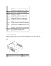
Jumper PSWD Setting 1 RTCRST 1 Description Password features are disabled. Password features are enabled (default setting). The real-time clock has been enabled (default setting). jumpered Desktop Computer unjumpered 2 1 3 4 6 5 1 drive bay (CD/DVD, floppy, 4 card slots and hard drive) 2 power supply 5 heat sink assembly 3 system board 6 front I/O panel Quick Reference Guide 27 The real-time clock is being reset (jumpered temporarily).
Jumper PSWD Setting 1 RTCRST 1 Description Password features are disabled. Password features are enabled (default setting). The real-time clock has been enabled (default setting). jumpered Desktop Computer unjumpered 2 1 3 4 6 5 1 drive bay (CD/DVD, floppy, 4 card slots and hard drive) 2 power supply 5 heat sink assembly 3 system board 6 front I/O panel Quick Reference Guide 27 The real-time clock is being reset (jumpered temporarily).

Quick Reference Guide
Page 33
...Dell, see your online User's Guide. For instructions on diagnosing the beep code see if the specific problem is identified (see "Diagnostic Lights" on page 34). times and then turns off Check Diagnostic Lights to see if the specific problem is operating normally. Blinking yellow A power supply... or system board failure has occurred. See "Power Problems" in a power-saving mode. Solid green and a beep code during POST Solid green power light and no beep code be faulty. 5...
...Dell, see your online User's Guide. For instructions on diagnosing the beep code see if the specific problem is identified (see "Diagnostic Lights" on page 34). times and then turns off Check Diagnostic Lights to see if the specific problem is operating normally. Blinking yellow A power supply... or system board failure has occurred. See "Power Problems" in a power-saving mode. Solid green and a beep code during POST Solid green power light and no beep code be faulty. 5...
User Guide
Page 23
... microphone connector is on the card. If you do not accidentally disconnect cables from the system board. 1 drives bay (CD/DVD, floppy, and hard drive) 2 power supply 3 system board 4 card slots 5 heat sink assembly 6 front I/O panel For more information, see System Setup Options. Connect a serial device, such as a handheld device, to attach...
... microphone connector is on the card. If you do not accidentally disconnect cables from the system board. 1 drives bay (CD/DVD, floppy, and hard drive) 2 power supply 3 system board 4 card slots 5 heat sink assembly 6 front I/O panel For more information, see System Setup Options. Connect a serial device, such as a handheld device, to attach...

User Guide
Page 40
... any of your computer, discharge static electricity from the system board and drives. Replace the screws that attach the power supply to Contents Page Power Supply Dell™ OptiPlex™ 320 User's Guide Replacing the Power Supply DC Power Connectors Replacing the Power Supply CAUTION: Before you touch any of the procedures in this section, follow the safety instructions located in Before...
... any of your computer, discharge static electricity from the system board and drives. Replace the screws that attach the power supply to Contents Page Power Supply Dell™ OptiPlex™ 320 User's Guide Replacing the Power Supply DC Power Connectors Replacing the Power Supply CAUTION: Before you touch any of the procedures in this section, follow the safety instructions located in Before...

User Guide
Page 47
... blinking light four lights on the front panel (see Diagnostic Lights) AUX_PWR on the system board Power DC power supply: Wattage Heat dissipation Voltage Backup battery 280 W 955 BTU/hr NOTE: Heat dissipation is calculated based upon the power supply wattage rating. 90 to 135 V at 60 Hz; 180 to 264 V at 50 Hz; 100...
... blinking light four lights on the front panel (see Diagnostic Lights) AUX_PWR on the system board Power DC power supply: Wattage Heat dissipation Voltage Backup battery 280 W 955 BTU/hr NOTE: Heat dissipation is calculated based upon the power supply wattage rating. 90 to 135 V at 60 Hz; 180 to 264 V at 50 Hz; 100...
User Guide
Page 70
... measurement of a floppy disk. One W is shut down your computer. A unit of cable used to protect against interference. You can supply 66 W of unshielded wires are read or written in the drive when the computer is 1 ampere of speakers, printer, broadband devices (... by enabling features such as Windows operating systems, displays in video modes that provides the video capabilities-in virus - watt-hour - uninterruptible power supply - video resolution - If the computer is eradicated. One V appears across a resistance of 1 ohm when a current of memory chips ...
... measurement of a floppy disk. One W is shut down your computer. A unit of cable used to protect against interference. You can supply 66 W of unshielded wires are read or written in the drive when the computer is 1 ampere of speakers, printer, broadband devices (... by enabling features such as Windows operating systems, displays in video modes that provides the video capabilities-in virus - watt-hour - uninterruptible power supply - video resolution - If the computer is eradicated. One V appears across a resistance of 1 ohm when a current of memory chips ...

User Guide
Page 75
Dell™ OptiPlex™ 320 User's Guide Mini Tower Computer About Your Computer Finding Information Mini Tower Computer Mini Tower Computer Specifications Advanced Features Cleaning Your Computer Connecting Multiple Monitors ... 2006 P/N JK524 Rev. A00 has determined that helps you make better use of Microsoft Corporation; Dell Inc. Only) Removing and Replacing Parts Before You Begin Removing the Computer Cover I/O Panel Drives PCI and PCI Express Cards Power Supply Processor Battery System Board Memory Replacing the Computer Cover Notes, Notices, and Cautions NOTE: A NOTE...
Dell™ OptiPlex™ 320 User's Guide Mini Tower Computer About Your Computer Finding Information Mini Tower Computer Mini Tower Computer Specifications Advanced Features Cleaning Your Computer Connecting Multiple Monitors ... 2006 P/N JK524 Rev. A00 has determined that helps you make better use of Microsoft Corporation; Dell Inc. Only) Removing and Replacing Parts Before You Begin Removing the Computer Cover I/O Panel Drives PCI and PCI Express Cards Power Supply Processor Battery System Board Memory Replacing the Computer Cover Notes, Notices, and Cautions NOTE: A NOTE...

User Guide
Page 79
CAUTION: To avoid electrical shock, always unplug your computer from the system board. 1 floppy drive 2 CD/DVD drive 3 power supply 4 system board 5 heat sink assembly 6 hard drive System Board Components 1 fan connector (FAN) 2 processor connector (CPU) 3 processor power connector (12VPOWER) 4 front-panel connector (FNT_PANEL) 5 memory module connectors (DIMM_1, DIMM_2) 10 internal buzzer (SPKR1) 11...
CAUTION: To avoid electrical shock, always unplug your computer from the system board. 1 floppy drive 2 CD/DVD drive 3 power supply 4 system board 5 heat sink assembly 6 hard drive System Board Components 1 fan connector (FAN) 2 processor connector (CPU) 3 processor power connector (12VPOWER) 4 front-panel connector (FNT_PANEL) 5 memory module connectors (DIMM_1, DIMM_2) 10 internal buzzer (SPKR1) 11...

User Guide
Page 102
...Page Power Supply Dell™ OptiPlex™ 320 User's Guide Replacing the Power Supply DC Power Connectors Replacing the Power Supply CAUTION: Before you begin any of the computer chassis. Disconnect the DC power cables from being pinched or crimped. 3. Remove the four screws that secure the power supply to..., follow the safety instructions located in the Product Information Guide. Lift the power supply up and out of the computer chassis. 1 release button 2 power supply 3 screws (4) 4 AC power connector 5. You must route these cables properly when you remove them from ...
...Page Power Supply Dell™ OptiPlex™ 320 User's Guide Replacing the Power Supply DC Power Connectors Replacing the Power Supply CAUTION: Before you begin any of the computer chassis. Disconnect the DC power cables from being pinched or crimped. 3. Remove the four screws that secure the power supply to..., follow the safety instructions located in the Product Information Guide. Lift the power supply up and out of the computer chassis. 1 release button 2 power supply 3 screws (4) 4 AC power connector 5. You must route these cables properly when you remove them from ...
User Guide
Page 103
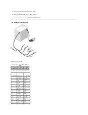
Connect the AC power cable to the power supply. 10. DC Power Connectors DC Power Connector P1 Pin Number Signal name 18-AWG Wire 1 +3.3 VDC Orange 2 +3.3 VDC Orange 3 GND Black 4 +5 VDC Red 5 GND Black 6 +5 VDC Red 7 GND Black 8 PS_PWRGOOD Gray 9 P5AUX Purple 10 +12 VDC White 11 +12 VDC White 12 +3.3 VDC Orange 13 +3.3 VDC Orange 14 -12 VDC Blue 15 GND Black 16 PWR_PS_ON Green 17 GND Black Reconnect the DC power cables to the AC power connector. 11. Replace the computer cover (see Replacing the Computer Cover). 9.
Connect the AC power cable to the power supply. 10. DC Power Connectors DC Power Connector P1 Pin Number Signal name 18-AWG Wire 1 +3.3 VDC Orange 2 +3.3 VDC Orange 3 GND Black 4 +5 VDC Red 5 GND Black 6 +5 VDC Red 7 GND Black 8 PS_PWRGOOD Gray 9 P5AUX Purple 10 +12 VDC White 11 +12 VDC White 12 +3.3 VDC Orange 13 +3.3 VDC Orange 14 -12 VDC Blue 15 GND Black 16 PWR_PS_ON Green 17 GND Black Reconnect the DC power cables to the AC power connector. 11. Replace the computer cover (see Replacing the Computer Cover). 9.

User Guide
Page 109
... integrated network adapter) Diagnostic lights Standby power light green light for 10-Mb operation and orange light for 100-Mb operation yellow blinking light four lights on the front panel (see Diagnostic Lights) AUX_PWR on the system board Power DC power supply: Wattage Heat dissipation Voltage Backup battery ...305 W 1041 BTU/hr NOTE: Heat dissipation is calculated based upon the power supply rating. 90 to 135 V at 60 Hz; 180 to 264 V at ...
... integrated network adapter) Diagnostic lights Standby power light green light for 10-Mb operation and orange light for 100-Mb operation yellow blinking light four lights on the front panel (see Diagnostic Lights) AUX_PWR on the system board Power DC power supply: Wattage Heat dissipation Voltage Backup battery ...305 W 1041 BTU/hr NOTE: Heat dissipation is calculated based upon the power supply rating. 90 to 135 V at 60 Hz; 180 to 264 V at ...

User Guide
Page 114
...has determined that helps you how to hardware or loss of data and tells you make better use of Dell Inc.; Dell™ OptiPlex™ 320 User's Guide Desktop Computer About Your Computer Finding Information Desktop Computer Desktop Computer Specifications Advanced Features Connecting Multiple ...own. Only) Removing and Replacing Parts Before You Begin Removing the Computer Cover I/O Panel Drives PCI and PCI Express Cards Power Supply Processor Battery System Board Memory Replacing the Computer Cover Notes, Notices, and Cautions NOTE: A NOTE indicates important information that this...
...has determined that helps you how to hardware or loss of data and tells you make better use of Dell Inc.; Dell™ OptiPlex™ 320 User's Guide Desktop Computer About Your Computer Finding Information Desktop Computer Desktop Computer Specifications Advanced Features Connecting Multiple ...own. Only) Removing and Replacing Parts Before You Begin Removing the Computer Cover I/O Panel Drives PCI and PCI Express Cards Power Supply Processor Battery System Board Memory Replacing the Computer Cover Notes, Notices, and Cautions NOTE: A NOTE indicates important information that this...

User Guide
Page 134
.... See Beep Codes for recovery completion, and then restart the computer. Light Pattern Problem Description The computer is identified (see Contacting Dell). A power supply or system board failure has occurred. A possible floppy or hard drive failure has Reseat all modules without error. occurred. Check the diagnostic lights to remove ...
.... See Beep Codes for recovery completion, and then restart the computer. Light Pattern Problem Description The computer is identified (see Contacting Dell). A power supply or system board failure has occurred. A possible floppy or hard drive failure has Reseat all modules without error. occurred. Check the diagnostic lights to remove ...


