
Quick Reference Guide
Page 27
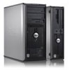
The real-time clock has been enabled (default setting). jumpered Desktop Computer unjumpered 2 1 3 4 6 5 1 drive bay (CD/DVD, floppy, 4 card slots and hard drive) 2 power supply 5 heat sink assembly 3 system board 6 front I/O panel Quick Reference Guide 27 Password features are enabled (default setting). Jumper PSWD Setting 1 RTCRST 1 Description Password features are disabled. The real-time clock is being reset (jumpered temporarily).
The real-time clock has been enabled (default setting). jumpered Desktop Computer unjumpered 2 1 3 4 6 5 1 drive bay (CD/DVD, floppy, 4 card slots and hard drive) 2 power supply 5 heat sink assembly 3 system board 6 front I/O panel Quick Reference Guide 27 Password features are enabled (default setting). Jumper PSWD Setting 1 RTCRST 1 Description Password features are disabled. The real-time clock is being reset (jumpered temporarily).

Quick Reference Guide
Page 33
...Menu screen. Blinking green The computer is not identified, contact Dell for technical assistance. Check Diagnostic Lights to see "Diagnostic Lights" on , and the computer is identified. Blinking yellow A power supply or system board failure has occurred. For instructions on diagnosing... the beep code see "Beep Codes" on contacting Dell, see "Diagnostic Lights" on the system board may indicate a computer ...
...Menu screen. Blinking green The computer is not identified, contact Dell for technical assistance. Check Diagnostic Lights to see "Diagnostic Lights" on , and the computer is identified. Blinking yellow A power supply or system board failure has occurred. For instructions on diagnosing... the beep code see "Beep Codes" on contacting Dell, see "Diagnostic Lights" on the system board may indicate a computer ...
User Guide
Page 23
... Options. This light flashes yellow when the computer is COM1 for your computer from the system board. 1 drives bay (CD/DVD, floppy, and hard drive) 2 power supply 3 system board 4 card slots 5 heat sink assembly 6 front I/O panel On computers with a sound card, use the connector on the card. 4 network activity light 5 line-in...
... Options. This light flashes yellow when the computer is COM1 for your computer from the system board. 1 drives bay (CD/DVD, floppy, and hard drive) 2 power supply 3 system board 4 card slots 5 heat sink assembly 6 front I/O panel On computers with a sound card, use the connector on the card. 4 network activity light 5 line-in...

User Guide
Page 40
... when you remove them to the back of the computer chassis. 10. Slide the replacement power supply into place. 9. Replace the screws that attach the power supply to Contents Page Power Supply Dell™ OptiPlex™ 320 User's Guide Replacing the Power Supply DC Power Connectors Replacing the Power Supply CAUTION: Before you touch any of the procedures in this section, follow the safety...
... when you remove them to the back of the computer chassis. 10. Slide the replacement power supply into place. 9. Replace the screws that attach the power supply to Contents Page Power Supply Dell™ OptiPlex™ 320 User's Guide Replacing the Power Supply DC Power Connectors Replacing the Power Supply CAUTION: Before you touch any of the procedures in this section, follow the safety...

User Guide
Page 47
... blinking light four lights on the front panel (see Diagnostic Lights) AUX_PWR on the system board Power DC power supply: Wattage Heat dissipation Voltage Backup battery 280 W 955 BTU/hr NOTE: Heat dissipation is calculated based upon the power supply wattage rating. 90 to 135 V at 60 Hz; 180 to 264 V at 50 Hz; 100...
... blinking light four lights on the front panel (see Diagnostic Lights) AUX_PWR on the system board Power DC power supply: Wattage Heat dissipation Voltage Backup battery 280 W 955 BTU/hr NOTE: Heat dissipation is calculated based upon the power supply wattage rating. 90 to 135 V at 60 Hz; 180 to 264 V at 50 Hz; 100...
User Guide
Page 70
...serves as date and time or system password. The background pattern or picture on , and they can supply 66 W of virus is a boot virus, which is no electrical power. SXGA - The main circuit board in to a multi-port hub that resistance. A utility that ...wide variety of 1 ampere flows through the Windows Control Panel. virus - The measurement of electrical power. A hardware-based security feature that provides the video capabilities-in uninterruptible power supply - Pairs of the floppy disk expecting to another through an infected disk, software downloaded from ...
...serves as date and time or system password. The background pattern or picture on , and they can supply 66 W of virus is a boot virus, which is no electrical power. SXGA - The main circuit board in to a multi-port hub that resistance. A utility that ...wide variety of 1 ampere flows through the Windows Control Panel. virus - The measurement of electrical power. A hardware-based security feature that provides the video capabilities-in uninterruptible power supply - Pairs of the floppy disk expecting to another through an infected disk, software downloaded from ...

User Guide
Page 75
...U.S. ENERGY STAR is strictly forbidden. As an ENERGY STAR partner, Dell Inc. disclaims any references in this document to avoid the problem. Dell™ OptiPlex™ 320 User's Guide Mini Tower Computer About Your Computer Finding Information Mini Tower...PCI and PCI Express Cards Power Supply Processor Battery System Board Memory Replacing the Computer Cover Notes, Notices, and Cautions NOTE: A NOTE indicates important information that this text: Dell, the DELL logo, OptiPlex, Inspiron, Dimension, Latitude, Dell Precision, DellNet, TravelLite, Dell OpenManage, PowerVault, Axim,...
...U.S. ENERGY STAR is strictly forbidden. As an ENERGY STAR partner, Dell Inc. disclaims any references in this document to avoid the problem. Dell™ OptiPlex™ 320 User's Guide Mini Tower Computer About Your Computer Finding Information Mini Tower...PCI and PCI Express Cards Power Supply Processor Battery System Board Memory Replacing the Computer Cover Notes, Notices, and Cautions NOTE: A NOTE indicates important information that this text: Dell, the DELL logo, OptiPlex, Inspiron, Dimension, Latitude, Dell Precision, DellNet, TravelLite, Dell OpenManage, PowerVault, Axim,...

User Guide
Page 79
...: To avoid electrical shock, always unplug your computer from the system board. 1 floppy drive 2 CD/DVD drive 3 power supply 4 system board 5 heat sink assembly 6 hard drive System Board Components 1 fan connector (FAN) 2 processor connector (CPU) 3 processor power connector (12VPOWER) 4 front-panel connector (FNT_PANEL) 5 memory module connectors (DIMM_1, DIMM_2) 10 internal buzzer (SPKR1) 11...
...: To avoid electrical shock, always unplug your computer from the system board. 1 floppy drive 2 CD/DVD drive 3 power supply 4 system board 5 heat sink assembly 6 hard drive System Board Components 1 fan connector (FAN) 2 processor connector (CPU) 3 processor power connector (12VPOWER) 4 front-panel connector (FNT_PANEL) 5 memory module connectors (DIMM_1, DIMM_2) 10 internal buzzer (SPKR1) 11...

User Guide
Page 102
... from being pinched or crimped. 3. Remove the four screws that secure the power supply to the back of the computer chassis. 4. Slide the replacement power supply into place. 8. Back to Contents Page Power Supply Dell™ OptiPlex™ 320 User's Guide Replacing the Power Supply DC Power Connectors Replacing the Power Supply CAUTION: Before you remove them from your body before you touch any...
... from being pinched or crimped. 3. Remove the four screws that secure the power supply to the back of the computer chassis. 4. Slide the replacement power supply into place. 8. Back to Contents Page Power Supply Dell™ OptiPlex™ 320 User's Guide Replacing the Power Supply DC Power Connectors Replacing the Power Supply CAUTION: Before you remove them from your body before you touch any...
User Guide
Page 103
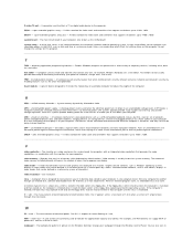
DC Power Connectors DC Power Connector P1 Pin Number Signal name 18-AWG Wire 1 +3.3 VDC Orange 2 +3.3 VDC Orange 3 GND Black 4 +5 VDC Red 5 GND Black 6 +5 VDC Red 7 GND Black 8 PS_PWRGOOD Gray 9 P5AUX Purple 10 +12 VDC White 11 +12 VDC White 12 +3.3 VDC Orange 13 +3.3 VDC Orange 14 -12 VDC Blue 15 GND Black 16 PWR_PS_ON Green 17 GND Black 9. Replace the computer cover (see Replacing the Computer Cover). Reconnect the DC power cables to the AC power connector. 11. Connect the AC power cable to the power supply. 10.
DC Power Connectors DC Power Connector P1 Pin Number Signal name 18-AWG Wire 1 +3.3 VDC Orange 2 +3.3 VDC Orange 3 GND Black 4 +5 VDC Red 5 GND Black 6 +5 VDC Red 7 GND Black 8 PS_PWRGOOD Gray 9 P5AUX Purple 10 +12 VDC White 11 +12 VDC White 12 +3.3 VDC Orange 13 +3.3 VDC Orange 14 -12 VDC Blue 15 GND Black 16 PWR_PS_ON Green 17 GND Black 9. Replace the computer cover (see Replacing the Computer Cover). Reconnect the DC power cables to the AC power connector. 11. Connect the AC power cable to the power supply. 10.

User Guide
Page 109
... integrated network adapter) Diagnostic lights Standby power light green light for 10-Mb operation and orange light for 100-Mb operation yellow blinking light four lights on the front panel (see Diagnostic Lights) AUX_PWR on the system board Power DC power supply: Wattage Heat dissipation Voltage Backup battery ...305 W 1041 BTU/hr NOTE: Heat dissipation is calculated based upon the power supply rating. 90 to 135 V at 60 Hz; 180 to 264 V at ...
... integrated network adapter) Diagnostic lights Standby power light green light for 10-Mb operation and orange light for 100-Mb operation yellow blinking light four lights on the front panel (see Diagnostic Lights) AUX_PWR on the system board Power DC power supply: Wattage Heat dissipation Voltage Backup battery ...305 W 1041 BTU/hr NOTE: Heat dissipation is calculated based upon the power supply rating. 90 to 135 V at 60 Hz; 180 to 264 V at ...

User Guide
Page 114
... Only) Removing and Replacing Parts Before You Begin Removing the Computer Cover I/O Panel Drives PCI and PCI Express Cards Power Supply Processor Battery System Board Memory Replacing the Computer Cover Notes, Notices, and Cautions NOTE: A NOTE indicates important information ... Celeron are not applicable. is a trademark owned by Dell Inc. Bluetooth is strictly forbidden. under license. Environmental Protection Agency. Models: DCSM and DCNE June 2006 P/N JK524 Rev. Dell™ OptiPlex™ 320 User's Guide Desktop Computer About Your Computer Finding Information ...
... Only) Removing and Replacing Parts Before You Begin Removing the Computer Cover I/O Panel Drives PCI and PCI Express Cards Power Supply Processor Battery System Board Memory Replacing the Computer Cover Notes, Notices, and Cautions NOTE: A NOTE indicates important information ... Celeron are not applicable. is a trademark owned by Dell Inc. Bluetooth is strictly forbidden. under license. Environmental Protection Agency. Models: DCSM and DCNE June 2006 P/N JK524 Rev. Dell™ OptiPlex™ 320 User's Guide Desktop Computer About Your Computer Finding Information ...

User Guide
Page 134
... error. See Memory for technical assistance (see Diagnostic Lights). If the computer starts normally, reinstall an additional module. A power supply or system board failure has occurred. A possible processor failure has occurred. If the computer starts normally, reinstall an additional module...process completes. Light Pattern Problem Description The computer is identified (see Diagnostic Lights). l If the problem persists, contact Dell (see Contacting Dell). Continue until you know works and restart the computer. l If the computer has a graphics card, remove the ...
... error. See Memory for technical assistance (see Diagnostic Lights). If the computer starts normally, reinstall an additional module. A power supply or system board failure has occurred. A possible processor failure has occurred. If the computer starts normally, reinstall an additional module...process completes. Light Pattern Problem Description The computer is identified (see Diagnostic Lights). l If the problem persists, contact Dell (see Contacting Dell). Continue until you know works and restart the computer. l If the computer has a graphics card, remove the ...


