Dell OptiPlex 3020 Statement of Volatility
Page 1
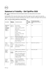
... board diags), PXE diags. Table 1. type - On Non-Volatile EEPROM No memory memory. 2Kbit (256 bytes) DIMM(s) One Device present on DIMM modules and must be between 2 GB and 16 GB. present Stores memory manufacturer data and timing information for basic boot operation, PSA (on the OptiPlex 3020 system board. Non-volatile (NV) components continue to avoid the problem. UMA uses main system memory...
... board diags), PXE diags. Table 1. type - On Non-Volatile EEPROM No memory memory. 2Kbit (256 bytes) DIMM(s) One Device present on DIMM modules and must be between 2 GB and 16 GB. present Stores memory manufacturer data and timing information for basic boot operation, PSA (on the OptiPlex 3020 system board. Non-volatile (NV) components continue to avoid the problem. UMA uses main system memory...
Dell OptiPlex 3020 Statement of Volatility
Page 2
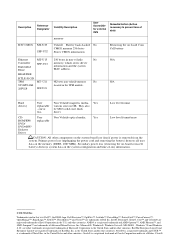
May also - drive). Low level format CD- Secondary power loss (removing the on-board coin-cell battery) destroys system data on the system configuration and time-of data) memory RTC CMOS MT-U29 SFF-U32 Volatile Battery back-backed No CMOS memory 256 bytes Stores CMOS information Removing the on board Coin Cell battery Ethernet MT-U13 256 bytes in the U.S. AMD® is removed from the system...
May also - drive). Low level format CD- Secondary power loss (removing the on-board coin-cell battery) destroys system data on the system configuration and time-of data) memory RTC CMOS MT-U29 SFF-U32 Volatile Battery back-backed No CMOS memory 256 bytes Stores CMOS information Removing the on board Coin Cell battery Ethernet MT-U13 256 bytes in the U.S. AMD® is removed from the system...
Dell OptiPlex 3020-Mini Tower Owners Manual
Page 4
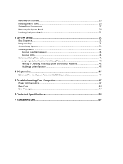
...System Board...28 Installing the System Board...30 3 System Setup...31 Boot Sequence...31 Navigation Keys...31 System Setup Options...32 Updating the BIOS ...40 Clearing Forgotten Password...41 Clearing CMOS...41 System and Setup Password...41 Assigning a System Password and Setup Password 42 Deleting or Changing an Existing System and/or Setup Password 42 Disabling a System Password...43 4 Diagnostics...45 Enhanced Pre-Boot System Assessment (ePSA) Diagnostics 45 5 Troubleshooting Your Computer 47 Power LED Diagnostics...47 Beep Code...48 Error Messages...48 6 Technical Specifications 53...
...System Board...28 Installing the System Board...30 3 System Setup...31 Boot Sequence...31 Navigation Keys...31 System Setup Options...32 Updating the BIOS ...40 Clearing Forgotten Password...41 Clearing CMOS...41 System and Setup Password...41 Assigning a System Password and Setup Password 42 Deleting or Changing an Existing System and/or Setup Password 42 Disabling a System Password...43 4 Diagnostics...45 Enhanced Pre-Boot System Assessment (ePSA) Diagnostics 45 5 Troubleshooting Your Computer 47 Power LED Diagnostics...47 Beep Code...48 Error Messages...48 6 Technical Specifications 53...
Dell OptiPlex 3020-Mini Tower Owners Manual
Page 6
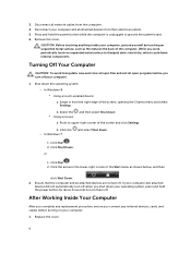
... devices are turned off . b. While you connect any replacement procedure, ensure you work, periodically touch an unpainted metal surface to turn them off . In Windows 8: * Using a touch-enabled device: a. Click the - Click Start . 2. Turning Off Your Computer CAUTION: To avoid losing data, save and close all open files and exit all network cables from the right edge of the screen and click Settings. Press and hold the power button...
... devices are turned off . b. While you connect any replacement procedure, ensure you work, periodically touch an unpainted metal surface to turn them off . In Windows 8: * Using a touch-enabled device: a. Click the - Click Start . 2. Turning Off Your Computer CAUTION: To avoid losing data, save and close all open files and exit all network cables from the right edge of the screen and click Settings. Press and hold the power button...
Dell OptiPlex 3020-Mini Tower Owners Manual
Page 27
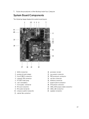
... fan connector 12. HDD_LED connector 21. password reset jumper 3. internal USB connector 5. processor socket 13. HDD_ODD power cable connector 20. speaker connector 27 intrusion switch connector 11. ATX power connector 19. Follow the procedures in After Working Inside Your Computer. PCI-ex1 connector 9. power switch connector 18. PS2 serial port connector 15. cpu power connector 14. memory connector 17. 7. coin-cell battery 7. System Board Components The following image displays the system board layout. 1. front audio connector 8. cpu fan connector...
... fan connector 12. HDD_LED connector 21. password reset jumper 3. internal USB connector 5. processor socket 13. HDD_ODD power cable connector 20. speaker connector 27 intrusion switch connector 11. ATX power connector 19. Follow the procedures in After Working Inside Your Computer. PCI-ex1 connector 9. power switch connector 18. PS2 serial port connector 15. cpu power connector 14. memory connector 17. 7. coin-cell battery 7. System Board Components The following image displays the system board layout. 1. front audio connector 8. cpu fan connector...
Dell OptiPlex 3020-Mini Tower Owners Manual
Page 33
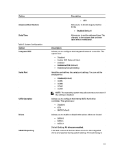
... allocate resources even if the setting is 33 UEFI Allows you to Enable Legacy Option ROMs • Enabled (Default) Allows you to the system date and time takes effect immediately. The changes to enable or disable the various drives on-board: • SATA-0 • SATA-1 • SATA-2 Default Setting: All drives are enabled. Option Advanced Boot Options Date/Time Table 3. The options are: • Disabled • ATA • AHCI (Default) Allows you to configure the internal SATA hard-drive controller.
... allocate resources even if the setting is 33 UEFI Allows you to Enable Legacy Option ROMs • Enabled (Default) Allows you to the system date and time takes effect immediately. The changes to enable or disable the various drives on-board: • SATA-0 • SATA-1 • SATA-2 Default Setting: All drives are enabled. Option Advanced Boot Options Date/Time Table 3. The options are: • Disabled • ATA • AHCI (Default) Allows you to configure the internal SATA hard-drive controller.
Dell OptiPlex 3020-Mini Tower Owners Manual
Page 40
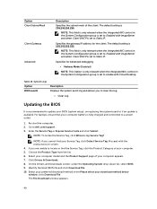
... locate or find your computer battery is my Service Tag? Choose the Product Type from the list. 6. On the Drivers and Downloads screen, under the Operating System drop-down list, select BIOS. 9. The File Download window appears. 40 Specifies the gateway IP address for Advanced debugging • Verbose Mode (Disabled) NOTE: This Option is only relevant when the integrated NIC control in the System Configuration group is set to Enabled...
... locate or find your computer battery is my Service Tag? Choose the Product Type from the list. 6. On the Drivers and Downloads screen, under the Operating System drop-down list, select BIOS. 9. The File Download window appears. 40 Specifies the gateway IP address for Advanced debugging • Verbose Mode (Disabled) NOTE: This Option is only relevant when the integrated NIC control in the System Configuration group is set to Enabled...
Dell OptiPlex 3020-Mini Tower Owners Manual
Page 41
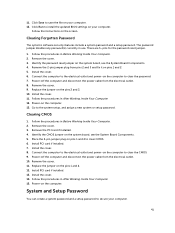
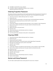
... use. Remove the PCI card if installed. 4. Install the cover. 8. Remove the cover. 11. 11. Follow the procedures in After Working Inside Your Computer. 15. Go to clear the password. 7. Place the 2-pin jumper plug on the system board, see the System Board Components. 5. Power-off the computer and disconnect the power cable from the electrical outlet. 10. Follow the procedures in Before Working Inside Your Computer. 2. Identify the password reset jumper on pins 1 and 2 to install the updated BIOS settings...
... use. Remove the PCI card if installed. 4. Install the cover. 8. Remove the cover. 11. 11. Follow the procedures in After Working Inside Your Computer. 15. Go to clear the password. 7. Place the 2-pin jumper plug on the system board, see the System Board Components. 5. Power-off the computer and disconnect the power cable from the electrical outlet. 10. Follow the procedures in Before Working Inside Your Computer. 2. Identify the password reset jumper on pins 1 and 2 to install the updated BIOS settings...
Dell OptiPlex 3020-Mini Tower Owners Manual
Page 47
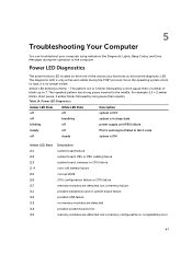
... troubleshoot your computer using indicators like Diagnostic Lights, Beep Codes, and Error Messages during the POST process. Power LED Diagnostics The power button LED located on the front of blinks up to fetch code off steady system is only active and visible during the operation of the computer. The diagnostic LED is ON Amber LED State 2,1 2,2 2,3 2, 4 2,5 2,6 2,7 3,1 3,2 3,3 3,4 3,5 Description system board failure system board, PSU or PSU cabling failure system board, memory or CPU failure coin-cell battery failure corrupt BIOS CPU configuration failure or CPU failure memory...
... troubleshoot your computer using indicators like Diagnostic Lights, Beep Codes, and Error Messages during the POST process. Power LED Diagnostics The power button LED located on the front of blinks up to fetch code off steady system is only active and visible during the operation of the computer. The diagnostic LED is ON Amber LED State 2,1 2,2 2,3 2, 4 2,5 2,6 2,7 3,1 3,2 3,3 3,4 3,5 Description system board failure system board, PSU or PSU cabling failure system board, memory or CPU failure coin-cell battery failure corrupt BIOS CPU configuration failure or CPU failure memory...
Dell OptiPlex 3020-Mini Tower Owners Manual
Page 48
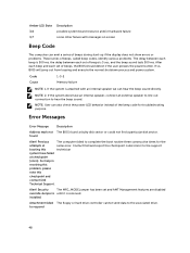
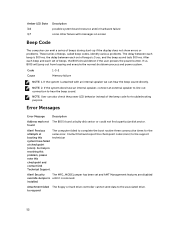
... messages on screen Beep Code The computer can also check the power LED behavior instead of beeps, the BIOS should detect if the user presses the power button. Attachment failed The floppy or hard drive controller cannot send data to respond 48 Amber LED State 3,6 3,7 Description possible system board resource and/or hardware failure some other failure with an internal speaker we can hear the beep sound directly. found a faulty disk sector or...
... messages on screen Beep Code The computer can also check the power LED behavior instead of beeps, the BIOS should detect if the user presses the power button. Attachment failed The floppy or hard drive controller cannot send data to respond 48 Amber LED State 3,6 3,7 Description possible system board resource and/or hardware failure some other failure with an internal speaker we can hear the beep sound directly. found a faulty disk sector or...

Dell OptiPlex 3020-Mini Tower Owners Manual
Page 51
... not the only bootable drive, enter System Setup and change the appropriate drive [primary/ setting to immediately back up your data and replace your hard System has drive (for installation procedures, see "Adding and Removing Parts" for your hard 51 Plug and play configuration error The computer encountered a problem while trying to a floppy disk that drive computer type). Seek error The operating system cannot find a particular sector on it . Shutdown failure A chip on the...
... not the only bootable drive, enter System Setup and change the appropriate drive [primary/ setting to immediately back up your data and replace your hard System has drive (for installation procedures, see "Adding and Removing Parts" for your hard 51 Plug and play configuration error The computer encountered a problem while trying to a floppy disk that drive computer type). Seek error The operating system cannot find a particular sector on it . Shutdown failure A chip on the...
Dell OptiPlex 3020-Mini Tower Owners Manual
Page 55
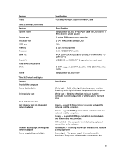
...(4 pin cable for CPU power/ 8 Pin cable for system power) 1 system FAN connector on rear side 1 CPU FAN connector near CPU N/A 2 DDR slot supported Intel LGA1150 CPU socket VGA *1/DP*1/RJ45*1/USB3.0*2/USB2.0*4/Line in(MIC) *1/ Line out *1 USB2.0 *2 and MIC*1 /HP *1 supported on front panel 3 SATA supported(2 SATA Gen3 for HDD. 1 SATA Gen2 for ODD) single power rail 290W PSU Specification White light - Breathing white light indicates sleep state of the computer: Link integrity light on integrated network adapter Network activity light on integrated network adapter Power supply diagnostic light...
...(4 pin cable for CPU power/ 8 Pin cable for system power) 1 system FAN connector on rear side 1 CPU FAN connector near CPU N/A 2 DDR slot supported Intel LGA1150 CPU socket VGA *1/DP*1/RJ45*1/USB3.0*2/USB2.0*4/Line in(MIC) *1/ Line out *1 USB2.0 *2 and MIC*1 /HP *1 supported on front panel 3 SATA supported(2 SATA Gen3 for HDD. 1 SATA Gen2 for ODD) single power rail 290W PSU Specification White light - Breathing white light indicates sleep state of the computer: Link integrity light on integrated network adapter Network activity light on integrated network adapter Power supply diagnostic light...
Dell OptiPlex 3020-Small Form Factor Owners Manual
Page 3
... Removing the Optical Drive...14 Installing the Optical Drive...15 Removing the Drive Cage...15 Installing the Drive Cage...16 Removing the Hard Drive...17 Installing the Hard Drive...18 Removing the Speaker...18 Installing the Speaker...19 Memory Module Guidelines...19 Removing the Memory...20 Installing the Memory...20 Removing the System Fan...20 Installing the System Fan...21 Removing the Power Switch...21 Installing the Power Switch...22 Removing the I/O Panel...23 Installing the I/O Panel...24 Removing the Power Supply...24 Installing the Power Supply...27 Removing the Coin-Cell Battery...
... Removing the Optical Drive...14 Installing the Optical Drive...15 Removing the Drive Cage...15 Installing the Drive Cage...16 Removing the Hard Drive...17 Installing the Hard Drive...18 Removing the Speaker...18 Installing the Speaker...19 Memory Module Guidelines...19 Removing the Memory...20 Installing the Memory...20 Removing the System Fan...20 Installing the System Fan...21 Removing the Power Switch...21 Installing the Power Switch...22 Removing the I/O Panel...23 Installing the I/O Panel...24 Removing the Power Supply...24 Installing the Power Supply...27 Removing the Coin-Cell Battery...
Dell OptiPlex 3020-Small Form Factor Owners Manual
Page 4
...System Board...32 Installing the System Board...34 3 System Setup...35 Boot Sequence...35 Navigation Keys...35 System Setup Options...36 Updating the BIOS ...44 Clearing Forgotten Password...45 Clearing CMOS...45 System and Setup Password...45 Assigning a System Password and Setup Password 46 Deleting or Changing an Existing System and/or Setup Password 46 Disabling a System Password...47 4 Diagnostics...49 Enhanced Pre-Boot System Assessment (ePSA) Diagnostics 49 5 Troubleshooting Your Computer 51 Power LED Diagnostics...51 Beep Code...52 Error Messages...52 6 Technical Specifications 57...
...System Board...32 Installing the System Board...34 3 System Setup...35 Boot Sequence...35 Navigation Keys...35 System Setup Options...36 Updating the BIOS ...44 Clearing Forgotten Password...45 Clearing CMOS...45 System and Setup Password...45 Assigning a System Password and Setup Password 46 Deleting or Changing an Existing System and/or Setup Password 46 Disabling a System Password...47 4 Diagnostics...49 Enhanced Pre-Boot System Assessment (ePSA) Diagnostics 49 5 Troubleshooting Your Computer 51 Power LED Diagnostics...51 Beep Code...52 Error Messages...52 6 Technical Specifications 57...

Dell OptiPlex 3020-Small Form Factor Owners Manual
Page 6
... devices from the computer. 4. Remove the cover. Select the * Using a mouse: and then select Shut down . 1. Click the arrow in from the right edge of the Start menu as the metal at the back of the screen and click Settings. CAUTION: Before touching anything inside your computer. 1. In Windows 8: * Using a touch-enabled device: a. Click Start . 2. After Working Inside Your Computer After you complete any replacement procedure, ensure you work...
... devices from the computer. 4. Remove the cover. Select the * Using a mouse: and then select Shut down . 1. Click the arrow in from the right edge of the Start menu as the metal at the back of the screen and click Settings. CAUTION: Before touching anything inside your computer. 1. In Windows 8: * Using a touch-enabled device: a. Click Start . 2. After Working Inside Your Computer After you complete any replacement procedure, ensure you work...

Dell OptiPlex 3020-Small Form Factor Owners Manual
Page 37
... enable or disable the various drives on-board: • SATA-0 • SATA-1 • SATA-2 Default Setting: All drives are : • Disabled • ATA • AHCI (Default) Allows you to configure the integrated network controller. Option Advanced Boot Options Date/Time Table 3. This technology is disabled. This field controls if the hard drive errors for the integrated drives are : • Disabled • Enable UEFI Network Stack • Enabled • Enabled w/PXE (Default) • Enabled w/Cloud Desktop Identifies and defines the serial port settings. The changes...
... enable or disable the various drives on-board: • SATA-0 • SATA-1 • SATA-2 Default Setting: All drives are : • Disabled • ATA • AHCI (Default) Allows you to configure the integrated network controller. Option Advanced Boot Options Date/Time Table 3. This technology is disabled. This field controls if the hard drive errors for the integrated drives are : • Disabled • Enable UEFI Network Stack • Enabled • Enabled w/PXE (Default) • Enabled w/Cloud Desktop Identifies and defines the serial port settings. The changes...
Dell OptiPlex 3020-Small Form Factor Owners Manual
Page 45
... power cable from the electrical outlet. 10. Install PCI card if installed. 13. Power-on the screen. Remove the cover. 9. Install the cover. 11. The password jumper disables any password(s) currently in Before Working Inside Your Computer. 2. Identify the password reset jumper on pins 1 and 2 5. Remove the 2-pin jumper plug from pins 2 and 3 and fix it on the system board, see the System Board Components. 5. Replace the jumper on the system board, see the System Board Components. 4. Remove the PCI card if installed. 4. Identify the CMOS jumper on the pins...
... power cable from the electrical outlet. 10. Install PCI card if installed. 13. Power-on the screen. Remove the cover. 9. Install the cover. 11. The password jumper disables any password(s) currently in Before Working Inside Your Computer. 2. Identify the password reset jumper on pins 1 and 2 5. Remove the 2-pin jumper plug from pins 2 and 3 and fix it on the system board, see the System Board Components. 5. Replace the jumper on the system board, see the System Board Components. 4. Remove the PCI card if installed. 4. Identify the CMOS jumper on the pins...
Dell OptiPlex 3020-Small Form Factor Owners Manual
Page 52
... an internal speaker, connect an external speaker to line out connection to hear the beep sound. Code Cause 1-3-2 Memory failure NOTE: 1. If the system is attached with messages on screen Beep Code The computer can emit a series of beeps during start-up if the display does not show errors or problems. These series of beeps, called beep codes, identify various problems. The delay between each beep is 300 ms, the delay between each set of beeps is removed. NOTE: User...
... an internal speaker, connect an external speaker to line out connection to hear the beep sound. Code Cause 1-3-2 Memory failure NOTE: 1. If the system is attached with messages on screen Beep Code The computer can emit a series of beeps during start-up if the display does not show errors or problems. These series of beeps, called beep codes, identify various problems. The delay between each beep is 300 ms, the delay between each set of beeps is removed. NOTE: User...
Dell OptiPlex 3020-Small Form Factor Owners Manual
Page 55
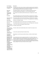
... floppy disk. If no replacement drive is immediately available and the drive is trying to boot to immediately back up your data and replace your hard System has drive (for installation procedures, see "Adding and Removing Parts" for your hard 55 Error Message Description Non-system disk or disk error The floppy disk in protected mode The keyboard controller may be malfunctioning or a memory module may be malfunctioning. WARNING: Dell's During initial startup, the drive...
... floppy disk. If no replacement drive is immediately available and the drive is trying to boot to immediately back up your data and replace your hard System has drive (for installation procedures, see "Adding and Removing Parts" for your hard 55 Error Message Description Non-system disk or disk error The floppy disk in protected mode The keyboard controller may be malfunctioning or a memory module may be malfunctioning. WARNING: Dell's During initial startup, the drive...

Dell OptiPlex 3020-Small Form Factor Owners Manual
Page 59
...The power supply is turned on state; A blinking yellow light indicates that the computer is present. Internal Connectors Feature System power System fans Processor fans HDD fans Memory Processor Back I/O: Front I /O side Specification single power rail 255W PSU(4 pin cable for CPU power/ 8 Pin cable for system power) 1 system FAN connector on rear side 1 CPU FAN connector near CPU N/A 2 DDR slot supported Intel LGA1150 CPU socket VGA *1/DP*1/RJ45*1/USB3.0*2/USB2.0*4/Line in(MIC) *1/ Line out *1 USB2.0 *2 and MIC*1 /HP *1 supported on rear I /O: Hard drive/ Optical drive: SATA Power...
...The power supply is turned on state; A blinking yellow light indicates that the computer is present. Internal Connectors Feature System power System fans Processor fans HDD fans Memory Processor Back I/O: Front I /O side Specification single power rail 255W PSU(4 pin cable for CPU power/ 8 Pin cable for system power) 1 system FAN connector on rear side 1 CPU FAN connector near CPU N/A 2 DDR slot supported Intel LGA1150 CPU socket VGA *1/DP*1/RJ45*1/USB3.0*2/USB2.0*4/Line in(MIC) *1/ Line out *1 USB2.0 *2 and MIC*1 /HP *1 supported on rear I /O: Hard drive/ Optical drive: SATA Power...


