
Service Manual
Page 8
Remove the PC Card or Express Card. Then close the protective door. 1.4 Screw Chart SCREW IMAGE PART NUMBER DESCRIPTION 18114 SHOULDER SCREW M2.5 18815 XFR LCD ASSY TOUCH SCREEN Qty/Assy Total Qty 6 6 18279 CHEESE HEAD SCREW M1.2 X 3 18806 18808 18812 AV DOOR ASSY VGA DOOR ASSY DVD DOOR ASSY 1 3 1 1 18353 SHOULDER SCREW-HEAT SPREADER 3 18035 HEAT SINK ASSY 3 18415 PAN HEAD SCREW M2.5 X 8 -BLACK 19 Page 8 of 106 Revision A01 d. DellTM XFR D630 Fully Rugged Notebook Service Manual PC Card Slot c.
Remove the PC Card or Express Card. Then close the protective door. 1.4 Screw Chart SCREW IMAGE PART NUMBER DESCRIPTION 18114 SHOULDER SCREW M2.5 18815 XFR LCD ASSY TOUCH SCREEN Qty/Assy Total Qty 6 6 18279 CHEESE HEAD SCREW M1.2 X 3 18806 18808 18812 AV DOOR ASSY VGA DOOR ASSY DVD DOOR ASSY 1 3 1 1 18353 SHOULDER SCREW-HEAT SPREADER 3 18035 HEAT SINK ASSY 3 18415 PAN HEAD SCREW M2.5 X 8 -BLACK 19 Page 8 of 106 Revision A01 d. DellTM XFR D630 Fully Rugged Notebook Service Manual PC Card Slot c.
Service Manual
Page 18
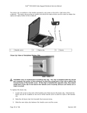
... the notebook 1 Handle cover 2 Stylus clip Close Up View of the handle cover. The clip is installed with the raised part towards the center of the notebook so that the raised part of the clip is within the recessed area of Installed Stylus Clip 3 Screw CAUTION: Care is needed when installing this... raised metal part of 106 Revision A01 To replace the stylus clip: 1. Page 18 of the clip is now above the handle cover housing, and you can be routed to attach the stylus and stylus tether to allow for right or left or right side of the notebook. DellTM XFR D630 Fully Rugged...
... the notebook 1 Handle cover 2 Stylus clip Close Up View of the handle cover. The clip is installed with the raised part towards the center of the notebook so that the raised part of the clip is within the recessed area of Installed Stylus Clip 3 Screw CAUTION: Care is needed when installing this... raised metal part of 106 Revision A01 To replace the stylus clip: 1. Page 18 of the clip is now above the handle cover housing, and you can be routed to attach the stylus and stylus tether to allow for right or left or right side of the notebook. DellTM XFR D630 Fully Rugged...
Service Manual
Page 44
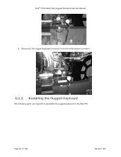
Disconnect the rugged keyboard connector from the motherboard connector. 8.2.2 Installing the Rugged Keyboard The following parts are required to assemble the rugged keyboard to the Dell XFR. DellTM XFR D630 Fully Rugged Notebook Service Manual 9. Page 44 of 106 Revision A01
Disconnect the rugged keyboard connector from the motherboard connector. 8.2.2 Installing the Rugged Keyboard The following parts are required to assemble the rugged keyboard to the Dell XFR. DellTM XFR D630 Fully Rugged Notebook Service Manual 9. Page 44 of 106 Revision A01

Service Manual
Page 63
... to apply the overlay. 3. Install the 2 screw covers to the new overlay. DellTM XFR D630 Fully Rugged Notebook Service Manual 1 display bezel overlay 4 display back cover 2 display bezel 3 display panel PART NUMBER 18428 18417 18114 SCREW TYPE CSK SCREW M2 X 8-BLACK PAN HEAD SCREW M2 X... 12-BLACK SHOULDER SCREW M2.5 QUANTITY 2 7 6 4. c. SCR,M2.5X10,PHH,MSCR,SHLDR,XFR NOTICE: Carefully separate the bezel from the bezel overlay. b....
... to apply the overlay. 3. Install the 2 screw covers to the new overlay. DellTM XFR D630 Fully Rugged Notebook Service Manual 1 display bezel overlay 4 display back cover 2 display bezel 3 display panel PART NUMBER 18428 18417 18114 SCREW TYPE CSK SCREW M2 X 8-BLACK PAN HEAD SCREW M2 X... 12-BLACK SHOULDER SCREW M2.5 QUANTITY 2 7 6 4. c. SCR,M2.5X10,PHH,MSCR,SHLDR,XFR NOTICE: Carefully separate the bezel from the bezel overlay. b....
Service Manual
Page 64
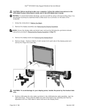
... (see Removing the Display Assembly). 12H NOTE: Ensure the display cable grommets were removed by following the grommet removal instructions provided in the XFR D630 User's Guide. Pull the LVDS cable thru the rubber grommet in Before You Begin. 12H 2. Follow the instructions in the LVDS/antenna ... cable to your computer, follow the safety instructions in the XFR D630 Product Information Guide and in Removing the Display Assembly at step 13. 123H 3. Remove hinges. Page 64 of the computer). 1. These antenna cables are part of the back cover assembly and must be separated from each...
... (see Removing the Display Assembly). 12H NOTE: Ensure the display cable grommets were removed by following the grommet removal instructions provided in the XFR D630 User's Guide. Pull the LVDS cable thru the rubber grommet in Before You Begin. 12H 2. Follow the instructions in the LVDS/antenna ... cable to your computer, follow the safety instructions in the XFR D630 Product Information Guide and in Removing the Display Assembly at step 13. 123H 3. Remove hinges. Page 64 of the computer). 1. These antenna cables are part of the back cover assembly and must be separated from each...

Service Manual
Page 65
... will have packing material covering the LVDS connector. Connect the LED cable. 2. On the right side, verify LVDS cable and antenna cables are part of the back cover assembly and must be taped to exit the top cover as shown above. 4. Align grommet on each side of the... exit the Display Assembly. NOTE: For optional Touch Screen Display panels, the touch controller cable is needed during tape removal. The new part will be separated from its packaging. On the left side hinge. Page 65 of the Display Panel. 7. DellTM XFR D630 Fully Rugged Notebook Service Manual 6.
... will have packing material covering the LVDS connector. Connect the LED cable. 2. On the right side, verify LVDS cable and antenna cables are part of the back cover assembly and must be taped to exit the top cover as shown above. 4. Align grommet on each side of the... exit the Display Assembly. NOTE: For optional Touch Screen Display panels, the touch controller cable is needed during tape removal. The new part will be separated from its packaging. On the left side hinge. Page 65 of the Display Panel. 7. DellTM XFR D630 Fully Rugged Notebook Service Manual 6.
Service Manual
Page 66
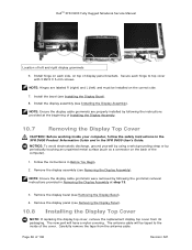
...will have a mylar covering. Install hinge on each hinge to the inside your computer, follow the safety instructions in the XFR D630 Product Information Guide and in the XFR D630 User's Guide. Remove the display panel (see Removing the Display Panel). 132H 10.8 Installing the Display Top Cover NOTE:... If replacing the display top cover, remove the replacement display top cover from the antenna cable. The new part will be installed on the...
...will have a mylar covering. Install hinge on each hinge to the inside your computer, follow the safety instructions in the XFR D630 Product Information Guide and in the XFR D630 User's Guide. Remove the display panel (see Removing the Display Panel). 132H 10.8 Installing the Display Top Cover NOTE:... If replacing the display top cover, remove the replacement display top cover from the antenna cable. The new part will be installed on the...
User Guide
Page 9
... or Mouse Problems 126 Video and Display Problems 127 If the display is blank 128 If the display is difficult to read 128 If only part of the display is readable 129 12 Intel® Active Management Technology 131 13 System Setup Program 135 Overview 135 Viewing the System Setup Screens...
... or Mouse Problems 126 Video and Display Problems 127 If the display is blank 128 If the display is difficult to read 128 If only part of the display is readable 129 12 Intel® Active Management Technology 131 13 System Setup Program 135 Overview 135 Viewing the System Setup Screens...

User Guide
Page 10
... Vista 144 Restoring Your Operating System 144 Using Microsoft® Windows® System Restore 145 Using the Operating System Media 146 15 Adding and Replacing Parts 149 Before You Begin 149 Recommended Tools 149 Turning Off Your Computer 149 Before Working Inside Your Computer 150 Hinge Cover 152 Keyboard 153 Internal...
... Vista 144 Restoring Your Operating System 144 Using Microsoft® Windows® System Restore 145 Using the Operating System Media 146 15 Adding and Replacing Parts 149 Before You Begin 149 Recommended Tools 149 Turning Off Your Computer 149 Before Working Inside Your Computer 150 Hinge Cover 152 Keyboard 153 Internal...
User Guide
Page 95
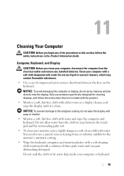
... water drip inside your computer or keyboard. 95 NOTICE: To prevent damage to remove dust from the electrical outlet and remove any of three parts water and one part dishwashing detergent. You can of compressed air to the antiglare coating, do not spray cleaning solution directly onto the display. 11 Cleaning Your...
... water drip inside your computer or keyboard. 95 NOTICE: To prevent damage to remove dust from the electrical outlet and remove any of three parts water and one part dishwashing detergent. You can of compressed air to the antiglare coating, do not spray cleaning solution directly onto the display. 11 Cleaning Your...
User Guide
Page 104
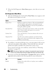
...page 193). If you want to increase the possibility of the problem. Tab Results Function Displays the results of devices. Dell Diagnostics Main Menu 1 After the Dell Diagnostics loads and the Main Menu screen appears, click the button for the option you cannot resolve the error condition,... description and follow the instructions on the symptom of the problem you run . Tests a specific device. If you contact Dell, technical support will ask for your part. Run Express Test first to run. This test typically takes 1 hour or more information. You can customize the tests ...
...page 193). If you want to increase the possibility of the problem. Tab Results Function Displays the results of devices. Dell Diagnostics Main Menu 1 After the Dell Diagnostics loads and the Main Menu screen appears, click the button for the option you cannot resolve the error condition,... description and follow the instructions on the symptom of the problem you run . Tests a specific device. If you contact Dell, technical support will ask for your part. Run Express Test first to run. This test typically takes 1 hour or more information. You can customize the tests ...
User Guide
Page 129
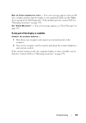
If an error message appears, see "Obtaining Assistance" on page 110. If only part of the display is not completely blank, run the Video device group in the Dell Diagnostics. Troubleshooting 129 If the problem persists, contact Dell (see "Error Messages" on page 193). RU N T H E VI D E O D I A G N O S T I C S T E ST S - If the...AN EXTERNAL MONITOR - 1 Shut down your computer and connect an external monitor to the computer. 2 Turn on page 193). Contact Dell (see "Obtaining Assistance" on the computer and the monitor and adjust the monitor brightness and contrast controls.
If an error message appears, see "Obtaining Assistance" on page 110. If only part of the display is not completely blank, run the Video device group in the Dell Diagnostics. Troubleshooting 129 If the problem persists, contact Dell (see "Error Messages" on page 193). RU N T H E VI D E O D I A G N O S T I C S T E ST S - If the...AN EXTERNAL MONITOR - 1 Shut down your computer and connect an external monitor to the computer. 2 Turn on page 193). Contact Dell (see "Obtaining Assistance" on the computer and the monitor and adjust the monitor brightness and contrast controls.
User Guide
Page 131
...Dell Client Manager 2.1 documentation at support.dell.com. Intel® Active Management Technology 131 Key benefits of iAMT are: • Reduced desk-side visits • Automation of more secure systems management capabilities that reduce IT costs, and allows better discovery, healing, and protection of networked computing assets. Intel Active Management Technology (iAMT), part...be configured using Dell Client Manager (DCM) 2.1. With iAMT, PCs can be managed whether the computer is turned on and off , or the operating system is available for Dell™ Latitude™ D630c ...
...Dell Client Manager 2.1 documentation at support.dell.com. Intel® Active Management Technology 131 Key benefits of iAMT are: • Reduced desk-side visits • Automation of more secure systems management capabilities that reduce IT costs, and allows better discovery, healing, and protection of networked computing assets. Intel Active Management Technology (iAMT), part...be configured using Dell Client Manager (DCM) 2.1. With iAMT, PCs can be managed whether the computer is turned on and off , or the operating system is available for Dell™ Latitude™ D630c ...
User Guide
Page 149
...1 Shut down the operating system: a Save and close any open files and exit any open programs before you turn off your Dell™ Product Information Guide. • A component can be replaced or-if purchased separately-installed by performing the removal procedure in your... computer. Adding and Replacing Parts 149 Unless otherwise noted, each procedure assumes that the following tools: • Small flat-blade screwdriver • Small Phillips screwdriver •...
...1 Shut down the operating system: a Save and close any open files and exit any open programs before you turn off your Dell™ Product Information Guide. • A component can be replaced or-if purchased separately-installed by performing the removal procedure in your... computer. Adding and Replacing Parts 149 Unless otherwise noted, each procedure assumes that the following tools: • Small flat-blade screwdriver • Small Phillips screwdriver •...
User Guide
Page 150
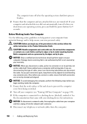
...-tab, not on a card. if you are disconnecting this section, follow the safety instructions in on page 149). 3 If the computer is not covered by Dell is connected to help protect your computer from your computer. CAUTION: Before you disconnect a cable, pull on its connector or on its pins. Some cables... not automatically turn off when you pull connectors apart, keep them evenly aligned to prevent the computer cover from the computer. 150 Adding and Replacing Parts
...-tab, not on a card. if you are disconnecting this section, follow the safety instructions in on page 149). 3 If the computer is not covered by Dell is connected to help protect your computer from your computer. CAUTION: Before you disconnect a cable, pull on its connector or on its pins. Some cables... not automatically turn off when you pull connectors apart, keep them evenly aligned to prevent the computer cover from the computer. 150 Adding and Replacing Parts
User Guide
Page 151
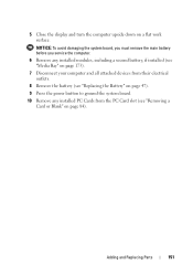
... system board. 10 Remove any installed PC Cards from the PC Card slot (see "Removing a Card or Blank" on a flat work surface. Adding and Replacing Parts 151 5 Close the display and turn the computer upside down on page 84).
... system board. 10 Remove any installed PC Cards from the PC Card slot (see "Removing a Card or Blank" on a flat work surface. Adding and Replacing Parts 151 5 Close the display and turn the computer upside down on page 84).
User Guide
Page 152
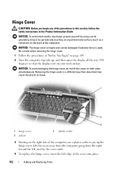
... the computer, use a plastic scribe to break. 1 2 3 1 hinge cover 3 indent 2 plastic scribe 3 Starting on the back of the cover into place. 152 Adding and Replacing Parts
... the computer, use a plastic scribe to break. 1 2 3 1 hinge cover 3 indent 2 plastic scribe 3 Starting on the back of the cover into place. 152 Adding and Replacing Parts
User Guide
Page 153
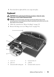
... (such as the back panel) on page 152). 1 2 3 4 5 6 1 screws (3) 2 keyboard tabs (5) 3 palm rest 4 pull-tab 5 keyboard-cable locking arm 6 keyboard cable connector Adding and Replacing Parts 153
... (such as the back panel) on page 152). 1 2 3 4 5 6 1 screws (3) 2 keyboard tabs (5) 3 palm rest 4 pull-tab 5 keyboard-cable locking arm 6 keyboard cable connector Adding and Replacing Parts 153
User Guide
Page 154
... installed. 1 Follow the procedures in "Before You Begin" on page 149. 2 Remove the hinge cover (see "Hinge Cover" on page 152). 154 Adding and Replacing Parts Internal Card With Bluetooth® Wireless Technology CAUTION: Before performing the following procedures, follow the safety instructions in your computer, it on the system board...
... installed. 1 Follow the procedures in "Before You Begin" on page 149. 2 Remove the hinge cover (see "Hinge Cover" on page 152). 154 Adding and Replacing Parts Internal Card With Bluetooth® Wireless Technology CAUTION: Before performing the following procedures, follow the safety instructions in your computer, it on the system board...
User Guide
Page 155
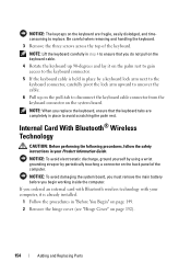
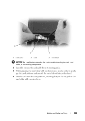
Adding and Replacing Parts 155 1 2 3 1 card cable 2 card 3 metal tab NOTICE: Be careful when removing the card to avoid damaging the card, card cable, or surrounding components. 3 Carefully remove the card cable from its routing guide. 4 While grasping the card cable with one hand, use a plastic scribe to gently pry the card out from underneath the metal tab with the other hand. 5 Lift the card from the compartment, ensuring that you do not pull on the card cable with excessive force.
Adding and Replacing Parts 155 1 2 3 1 card cable 2 card 3 metal tab NOTICE: Be careful when removing the card to avoid damaging the card, card cable, or surrounding components. 3 Carefully remove the card cable from its routing guide. 4 While grasping the card cable with one hand, use a plastic scribe to gently pry the card out from underneath the metal tab with the other hand. 5 Lift the card from the compartment, ensuring that you do not pull on the card cable with excessive force.


