
Service Manual
Page 45
... - Remove the display gaskets using your plastic scribe. Disconnect the LVDS cable from LCD panel antenna 7. Page 45 J5 J4 J4 Black - WWAN (from the motherboard. 6. Dell™ Latitude™ E6400 XFR Service Manual 2 1 4 3 1 LVDS connector & cable 2 WPAN cable 3 WLAN cable 4 WWAN cable 5.
... - Remove the display gaskets using your plastic scribe. Disconnect the LVDS cable from LCD panel antenna 7. Page 45 J5 J4 J4 Black - WWAN (from the motherboard. 6. Dell™ Latitude™ E6400 XFR Service Manual 2 1 4 3 1 LVDS connector & cable 2 WPAN cable 3 WLAN cable 4 WWAN cable 5.
Service Manual
Page 48
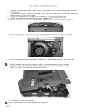
... M2.5 x 5-mm screw on the motherboard between the fan and the fan connector. 12. Disconnect the contactless smartcard cable from the system board. 7. NOTE: There are four snap hooks located in front of the mouse touchpad as part of the palm rest, until the snap release. 13. Dell™ Latitude™ E6400 XFR Service Manual 6.
... M2.5 x 5-mm screw on the motherboard between the fan and the fan connector. 12. Disconnect the contactless smartcard cable from the system board. 7. NOTE: There are four snap hooks located in front of the mouse touchpad as part of the palm rest, until the snap release. 13. Dell™ Latitude™ E6400 XFR Service Manual 6.
Service Manual
Page 49
...the procedures in the GPS tray. 1 2 1 USB cable channel guide 2 GPS passthru antenna cable guide 2. Align the palm rest on the motherboard between the fan and the fan connector. 8. Reconnect the GPS antenna and USB connector (optional: see Replacing the Display Assembly). 13. Apply slight ... 10. Route the GPS antenna and USB connector through the channel guides in After Working on the top of the computer. 7. Dell™ Latitude™ E6400 XFR Service Manual 21.2 Replacing the Palm Rest CAUTION: Before you begin any of the mousepad buttons until the snaps located below snap ...
...the procedures in the GPS tray. 1 2 1 USB cable channel guide 2 GPS passthru antenna cable guide 2. Align the palm rest on the motherboard between the fan and the fan connector. 8. Reconnect the GPS antenna and USB connector (optional: see Replacing the Display Assembly). 13. Apply slight ... 10. Route the GPS antenna and USB connector through the channel guides in After Working on the top of the computer. 7. Dell™ Latitude™ E6400 XFR Service Manual 21.2 Replacing the Palm Rest CAUTION: Before you begin any of the mousepad buttons until the snaps located below snap ...
Service Manual
Page 60
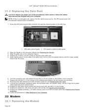
... and RJ-11 cable out of the way. 1 1 Wi-Fi Sniffer cable connection to motherboard 6. Remove the bottom access panel, LCD cable channel covers, display assembly, led cover, palm rest overlay, keyboard and palm rest (see Replacing the Palm Rest). 6. Remove the M2 x 3-mm screw from the motherboard. 4. Dell™ Latitude™ E6400 XFR Service Manual 3.
... and RJ-11 cable out of the way. 1 1 Wi-Fi Sniffer cable connection to motherboard 6. Remove the bottom access panel, LCD cable channel covers, display assembly, led cover, palm rest overlay, keyboard and palm rest (see Replacing the Palm Rest). 6. Remove the M2 x 3-mm screw from the motherboard. 4. Dell™ Latitude™ E6400 XFR Service Manual 3.

Service Manual
Page 61
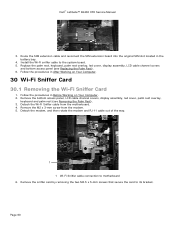
... the sniffer card with your computer. 1. Remove the sniffer card (see Removing the Modem). 4. Dell™ Latitude™ E6400 XFR Service Manual 1 1 M2.5 x 5-mm screws (2) 30.2 Replacing the Wi-Fi Sniffer Card 1. Connect the Wi-Fi sniffer cable to the motherboard. 3. Follow the procedures in this section, follow the safety instructions that shipped with its...
... the sniffer card with your computer. 1. Remove the sniffer card (see Removing the Modem). 4. Dell™ Latitude™ E6400 XFR Service Manual 1 1 M2.5 x 5-mm screws (2) 30.2 Replacing the Wi-Fi Sniffer Card 1. Connect the Wi-Fi sniffer cable to the motherboard. 3. Follow the procedures in this section, follow the safety instructions that shipped with its...


