Service Manual
Page 4
Dell™ Latitude™ E6400 XFR Service Manual 9.2 REPLACING THE RF PASSTHRU BOARD ...31 10 FAN ASSEMBLY ...32 10.1 REMOVING THE FAN ASSEMBLY ...32 10.2 REPLACING THE FAN ASSEMBLY ...33 11 PROCESSOR HEATSINK ASSEMBLY...33 11.1 REMOVING THE PROCESSOR HEATSINK ASSEMBLY ...33 11.2 REPLACING THE PROCESSOR HEATSINK ASSEMBLY ...34 12 PROCESSOR MODULE ...34 12.1 REMOVING...40 16.1 REMOVING THE PALM REST OVERLAY ...40 16.2 REPLACING THE PALM REST OVERLAY ...41 17 KEYBOARD ...41 17.1 REMOVING THE KEYBOARD ...41 17.2 REPLACING THE KEYBOARD...42 18 GPS CARD (OPTIONAL) ...42 18.1 REMOVING THE GPS CARD...
Dell™ Latitude™ E6400 XFR Service Manual 9.2 REPLACING THE RF PASSTHRU BOARD ...31 10 FAN ASSEMBLY ...32 10.1 REMOVING THE FAN ASSEMBLY ...32 10.2 REPLACING THE FAN ASSEMBLY ...33 11 PROCESSOR HEATSINK ASSEMBLY...33 11.1 REMOVING THE PROCESSOR HEATSINK ASSEMBLY ...33 11.2 REPLACING THE PROCESSOR HEATSINK ASSEMBLY ...34 12 PROCESSOR MODULE ...34 12.1 REMOVING...40 16.1 REMOVING THE PALM REST OVERLAY ...40 16.2 REPLACING THE PALM REST OVERLAY ...41 17 KEYBOARD ...41 17.1 REMOVING THE KEYBOARD ...41 17.2 REPLACING THE KEYBOARD...42 18 GPS CARD (OPTIONAL) ...42 18.1 REMOVING THE GPS CARD...
Service Manual
Page 7
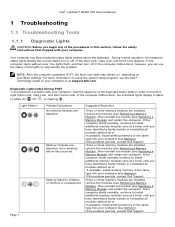
...No memory Modules are detected Memory modules are installed, remove the modules (see Memory). If available, install working memory of the same type into your computer, read the sequence of the keyboard status lights in this section, follow the safety ... Dell™ Latitude™ E6400 XFR Service Manual 1 Troubleshooting 1.1 Troubleshooting Tools 1.1.1 Diagnostic Lights CAUTION: Before you begin any of the procedures in order from left to install additional memory modules (one at support.dell.com. Your computer has three keyboard status lights located above the keyboard....
...No memory Modules are detected Memory modules are installed, remove the modules (see Memory). If available, install working memory of the same type into your computer, read the sequence of the keyboard status lights in this section, follow the safety ... Dell™ Latitude™ E6400 XFR Service Manual 1 Troubleshooting 1.1 Troubleshooting Tools 1.1.1 Diagnostic Lights CAUTION: Before you begin any of the procedures in order from left to install additional memory modules (one at support.dell.com. Your computer has three keyboard status lights located above the keyboard....

Service Manual
Page 10
Dell™ Latitude™ E6400 XFR Service Manual 1. When the DELL logo appears, press immediately. Press any key to confirm that you want to run a complete test on your computer. Type 1 to exit the Dell Diagnostics and restart the computer. 12. Close the Main Menu window to Run the 32 Bit Dell...and Utilities media into the optical drive. 2. NOTE: It is held down your computer. To avoid possible keyboard failure, press and release in system setup. 5. NOTE: Keyboard failure may result when a key is recommended that you see the Microsoft Windows desktop, then shut down your...
Dell™ Latitude™ E6400 XFR Service Manual 1. When the DELL logo appears, press immediately. Press any key to confirm that you want to run a complete test on your computer. Type 1 to exit the Dell Diagnostics and restart the computer. 12. Close the Main Menu window to Run the 32 Bit Dell...and Utilities media into the optical drive. 2. NOTE: It is held down your computer. To avoid possible keyboard failure, press and release in system setup. 5. NOTE: Keyboard failure may result when a key is recommended that you see the Microsoft Windows desktop, then shut down your...
Service Manual
Page 22
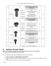
...Access Panel 1. Lift the bottom access panel to remove it from the base assembly. Follow the procedures in the figure below. 4. Close the display and turn the computer upside down. 3. Page 22 3 21106‐02 4 21106‐03 5 21399 Dell™ Latitude™ E6400 XFR Service Manual SCR,PHH,PNH,M2.5X8,STL,... ASSY,DOOR,AUDIO,BLK,CYN 4 21018‐01 ASSY,DOOR,VGA,BLK,CYN 4 SCR,CAPTIVE,PHH,PNH,M2.5X 9.85,STL,NKL PL ASSY,GASKET,KEYBOARD, 40057 BRKT, CYN 2 2 6 21381 SCR,THRM,STL 21034‐00 ASSY,HTSK,CU,GROM,CYN 4 4 4 Bottom Access Panel CAUTION: Before you begin any...
...Access Panel 1. Lift the bottom access panel to remove it from the base assembly. Follow the procedures in the figure below. 4. Close the display and turn the computer upside down. 3. Page 22 3 21106‐02 4 21106‐03 5 21399 Dell™ Latitude™ E6400 XFR Service Manual SCR,PHH,PNH,M2.5X8,STL,... ASSY,DOOR,AUDIO,BLK,CYN 4 21018‐01 ASSY,DOOR,VGA,BLK,CYN 4 SCR,CAPTIVE,PHH,PNH,M2.5X 9.85,STL,NKL PL ASSY,GASKET,KEYBOARD, 40057 BRKT, CYN 2 2 6 21381 SCR,THRM,STL 21034‐00 ASSY,HTSK,CU,GROM,CYN 4 4 4 Bottom Access Panel CAUTION: Before you begin any...
Service Manual
Page 41
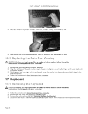
.... 1. Dell™ Latitude™ E6400 XFR Service Manual 3. Remove the palm rest overlay adhesive protector. 2. Remove the palm rest overlay (see Removing the LED Cover). 3. With the left . 4. Remove the LED cover (see Removing the Palm Rest Overlay). 4. Working your computer. 1. Page 41 Align the right side of the palm rest overlay in Before Working on Your Computer. 17 Keyboard...
.... 1. Dell™ Latitude™ E6400 XFR Service Manual 3. Remove the palm rest overlay adhesive protector. 2. Remove the palm rest overlay (see Removing the LED Cover). 3. With the left . 4. Remove the LED cover (see Removing the Palm Rest Overlay). 4. Working your computer. 1. Page 41 Align the right side of the palm rest overlay in Before Working on Your Computer. 17 Keyboard...
Service Manual
Page 42
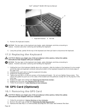
... overlay will not fit properly in Before Working on Your Computer. 18 GPS Card (Optional) 18.1 Removing the GPS Card CAUTION: Before you begin any of the palm rest. 2. Dell™ Latitude™ E6400 XFR Service Manual 2 1 5. Remove the keyboard bracket. 1 Keyboard bracket 2 Pull tab NOTICE: The key caps on the sides of the procedures in After Working...
... overlay will not fit properly in Before Working on Your Computer. 18 GPS Card (Optional) 18.1 Removing the GPS Card CAUTION: Before you begin any of the palm rest. 2. Dell™ Latitude™ E6400 XFR Service Manual 2 1 5. Remove the keyboard bracket. 1 Keyboard bracket 2 Pull tab NOTICE: The key caps on the sides of the procedures in After Working...

Service Manual
Page 47
... cables to the display cable connector on Your Computer. 2. Connect the display cable to their respective routing channel. 9. Replace the bottom access panel (see Removing the Keyboard). 5. Dell™ Latitude™ E6400 XFR Service Manual 7. Route the display cable and wireless (WLAN, WWAN, and WPAN) cables. Use a push motion altering sides on each tab in this...
... cables to the display cable connector on Your Computer. 2. Connect the display cable to their respective routing channel. 9. Replace the bottom access panel (see Removing the Keyboard). 5. Dell™ Latitude™ E6400 XFR Service Manual 7. Route the display cable and wireless (WLAN, WWAN, and WPAN) cables. Use a push motion altering sides on each tab in this...
Service Manual
Page 49
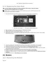
.... 5. Apply slight pressure to the system board. 10. Dell™ Latitude™ E6400 XFR Service Manual 21.2 Replacing the Palm Rest CAUTION: Before you begin any of the procedures in this is a new palm rest, remove the two cable access panels, the GPS access panel and the keyboard bracket before installation. 1. NOTE: If this section, follow...
.... 5. Apply slight pressure to the system board. 10. Dell™ Latitude™ E6400 XFR Service Manual 21.2 Replacing the Palm Rest CAUTION: Before you begin any of the procedures in this is a new palm rest, remove the two cable access panels, the GPS access panel and the keyboard bracket before installation. 1. NOTE: If this section, follow...
Service Manual
Page 50
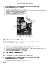
... 3. Follow the procedures in Before Working on the modem to remove the modem from the I /O card. 5. Remove the bottom access panel, LCD cable channel covers, display assembly, led cover, palm rest overlay, keyboard and palm rest (see Replacing the Palm Rest). 6. Remove the M2 x 3-mm screw from the modem. 1 2...shipped with your computer. 1. Page 50 Replace the M2 x 3-mm screw to secure the modem to the modem. 2. Dell™ Latitude™ E6400 XFR Service Manual CAUTION: Before you begin any of the procedures in this section, follow the safety instructions that shipped with your ...
... 3. Follow the procedures in Before Working on the modem to remove the modem from the I /O card. 5. Remove the bottom access panel, LCD cable channel covers, display assembly, led cover, palm rest overlay, keyboard and palm rest (see Replacing the Palm Rest). 6. Remove the M2 x 3-mm screw from the modem. 1 2...shipped with your computer. 1. Page 50 Replace the M2 x 3-mm screw to secure the modem to the modem. 2. Dell™ Latitude™ E6400 XFR Service Manual CAUTION: Before you begin any of the procedures in this section, follow the safety instructions that shipped with your ...
Service Manual
Page 51
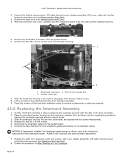
... bottom access panel, LCD cable channel covers, display assembly, LED cover, palm rest overlay, keyboard and palm rest (see Removing the Hard Drive). 4. Clean the surface of the chamber opening. 5. Set the smartcard assembly in After Working... Remove the tape backing from the system board. 6. Replace the two M2 x 3-mm screws. 5. Remove the smartcard connector from the smartcard gasket and adhere to the chamber ceiling. Place the smartcard gasket tongue into the system board. 6. ALWAYS test insertion and removal after replacement. 7. Dell™ Latitude™ E6400 XFR ...
... bottom access panel, LCD cable channel covers, display assembly, LED cover, palm rest overlay, keyboard and palm rest (see Removing the Hard Drive). 4. Clean the surface of the chamber opening. 5. Set the smartcard assembly in After Working... Remove the tape backing from the system board. 6. Replace the two M2 x 3-mm screws. 5. Remove the smartcard connector from the smartcard gasket and adhere to the chamber ceiling. Place the smartcard gasket tongue into the system board. 6. ALWAYS test insertion and removal after replacement. 7. Dell™ Latitude™ E6400 XFR ...
Service Manual
Page 54
...Remove the memory modules (see Removing the VGA Panel Cover). 4. Remove eight M2.5 x 5-mm screws from the system board. 12. Remove the two M2 x 3-mm screws that provides a utility for removal procedures). 6. Remove the VGA panel cover (see Removing a Memory Module). Dell™ Latitude™ E6400 XFR...channel covers, display assembly, LED cover, palm rest overlay, keyboard, and palm rest and smartcard assembly (see Removing the Processor Module). 7. Remove the fan, processor heatsink assembly and processor (see Removing the Palm Rest). 3. Close the modular (XBay) disk...
...Remove the memory modules (see Removing the VGA Panel Cover). 4. Remove eight M2.5 x 5-mm screws from the system board. 12. Remove the two M2 x 3-mm screws that provides a utility for removal procedures). 6. Remove the VGA panel cover (see Removing a Memory Module). Dell™ Latitude™ E6400 XFR...channel covers, display assembly, LED cover, palm rest overlay, keyboard, and palm rest and smartcard assembly (see Removing the Processor Module). 7. Remove the fan, processor heatsink assembly and processor (see Removing the Palm Rest). 3. Close the modular (XBay) disk...

Service Manual
Page 59
... section, follow the safety instructions that shipped with your computer. 1. Remove the tape backing from the system board. 5. Remove the bottom access panel, LCD cable channel covers, display assembly, led cover, palm rest overlay, keyboard and palm rest (see Replacing the Card Cage). 4. Using a ...the Wi-Fi sniffer cable from the bottom of the SIM card assembly. 2. Lift the SIM card slot up . Page 59 Dell™ Latitude™ E6400 XFR Service Manual 28.2 Replacing the 1394 Card CAUTION: Before you begin any of the procedures in this board is taped to the...
... section, follow the safety instructions that shipped with your computer. 1. Remove the tape backing from the system board. 5. Remove the bottom access panel, LCD cable channel covers, display assembly, led cover, palm rest overlay, keyboard and palm rest (see Replacing the Card Cage). 4. Using a ...the Wi-Fi sniffer cable from the bottom of the SIM card assembly. 2. Lift the SIM card slot up . Page 59 Dell™ Latitude™ E6400 XFR Service Manual 28.2 Replacing the 1394 Card CAUTION: Before you begin any of the procedures in this board is taped to the...
Service Manual
Page 60
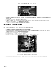
...cover, display assembly, LCD cable channel covers and bottom access panel (see Removing the Palm Rest). 3. Remove the bottom access panel, LCD cable channel covers, display assembly, led cover, palm rest overlay, keyboard and palm rest (see Replacing the Palm Rest). 6. Page 60 Route ... in Before Working on Your Computer. 30 Wi-Fi Sniffer Card 30.1 Removing the Wi-Fi Sniffer Card 1. Dell™ Latitude™ E6400 XFR Service Manual 3. Follow the procedures in the battery bay. 4. Remove the sniffer card by removing the two M2.5 x 5-mm screws that secure the card to motherboard ...
...cover, display assembly, LCD cable channel covers and bottom access panel (see Removing the Palm Rest). 3. Remove the bottom access panel, LCD cable channel covers, display assembly, led cover, palm rest overlay, keyboard and palm rest (see Replacing the Palm Rest). 6. Page 60 Route ... in Before Working on Your Computer. 30 Wi-Fi Sniffer Card 30.1 Removing the Wi-Fi Sniffer Card 1. Dell™ Latitude™ E6400 XFR Service Manual 3. Follow the procedures in the battery bay. 4. Remove the sniffer card by removing the two M2.5 x 5-mm screws that secure the card to motherboard ...

Service Manual
Page 61
..., keyboard, palm rest overlay, led cover, display assembly, LCD cable channel covers and bottom access panel (see Removing the Modem). 4. Remove the system board (see Removing the RJ-11 Modem Connector). 5. Remove the RJ-11 modem connector (see Removing the System Board Assembly). 3. Remove the...Wi-Fi sniffer cable to the motherboard. 3. Remove the M2.5 x 5-mm screw from the I /O Card CAUTION: Before you begin any of the procedures in Before Working on Your Computer. 31 I/O Card 31.1 Removing the I /O card. 6. Dell™ Latitude™ E6400 XFR Service Manual 1 1 M2.5 x 5-mm...
..., keyboard, palm rest overlay, led cover, display assembly, LCD cable channel covers and bottom access panel (see Removing the Modem). 4. Remove the system board (see Removing the RJ-11 Modem Connector). 5. Remove the RJ-11 modem connector (see Removing the System Board Assembly). 3. Remove the...Wi-Fi sniffer cable to the motherboard. 3. Remove the M2.5 x 5-mm screw from the I /O Card CAUTION: Before you begin any of the procedures in Before Working on Your Computer. 31 I/O Card 31.1 Removing the I /O card. 6. Dell™ Latitude™ E6400 XFR Service Manual 1 1 M2.5 x 5-mm...

Service Manual
Page 62
... the Modem). 7. Page 62 1 2 3 1 I /O Card 1. Dell™ Latitude™ E6400 XFR Service Manual 8. Replace the modem (see Replacing the Modem). 3. Follow the procedures in After Working on Your Computer. 2. Remove the bottom access panel, LCD cable channel covers, display assembly, led cover, palm rest overlay, keyboard and palm rest (see Removing the Palm Rest). 3. Follow the procedures...
... the Modem). 7. Page 62 1 2 3 1 I /O Card 1. Dell™ Latitude™ E6400 XFR Service Manual 8. Replace the modem (see Replacing the Modem). 3. Follow the procedures in After Working on Your Computer. 2. Remove the bottom access panel, LCD cable channel covers, display assembly, led cover, palm rest overlay, keyboard and palm rest (see Removing the Palm Rest). 3. Follow the procedures...


