Owner's Manual
Page 4
......46 Removing the LVDS and Camera Cable...47 Installing the LVDS and Camera Cable...48 3 Additional Information...49 Docking Port Information...49 4 System Setup...51 Boot Sequence...51 Navigation Keys...51 System Setup Options...52 Updating the BIOS ...59 System and Setup Password...60 Assigning a System Password and Setup Password 60...
......46 Removing the LVDS and Camera Cable...47 Installing the LVDS and Camera Cable...48 3 Additional Information...49 Docking Port Information...49 4 System Setup...51 Boot Sequence...51 Navigation Keys...51 System Setup Options...52 Updating the BIOS ...59 System and Setup Password...60 Assigning a System Password and Setup Password 60...
Owner's Manual
Page 51
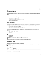
... arrow Moves to access the System Setup screen. The boot sequence screen also displays the option to the next field. 51 Navigation Keys The following table displays the system setup navigation keys. During the Power-on Self Test (POST), when the Dell logo appears, you can: • Access System Setup... by pressing key • Bring up the one-time boot menu by pressing key The one-time boot menu displays the devices that you make are : • Removable Drive (...
... arrow Moves to access the System Setup screen. The boot sequence screen also displays the option to the next field. 51 Navigation Keys The following table displays the system setup navigation keys. During the Power-on Self Test (POST), when the Dell logo appears, you can: • Access System Setup... by pressing key • Bring up the one-time boot menu by pressing key The one-time boot menu displays the devices that you make are : • Removable Drive (...

Owner's Manual
Page 52
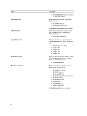
...• Internal HDD • USB Storage Device • CD/DVD/CD-RW Drive • Onboard NIC You can also choose the Boot List option. Moves to configure the integrated network controller. Displays the System Setup help file. Allows you to change the order in this ... NOTE: Depending on your computer. • System Information • Memory Information • Processor Information • Device Information Battery Information Boot Sequence Displays the charge status of your computer and its installed devices, the items listed in which the computer attempts to find an operating...
...• Internal HDD • USB Storage Device • CD/DVD/CD-RW Drive • Onboard NIC You can also choose the Boot List option. Moves to configure the integrated network controller. Displays the System Setup help file. Allows you to change the order in this ... NOTE: Depending on your computer. • System Information • Memory Information • Processor Information • Device Information Battery Information Boot Sequence Displays the charge status of your computer and its installed devices, the items listed in which the computer attempts to find an operating...
Owner's Manual
Page 54
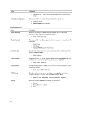
...; Level is 75% • Level is disabled by default. • Enable USB PowerShare Allows you to define the USB configuration. The options are: • Enable Boot Support • Enable External USB Port Default Setting: both the options are enabled. The option is disabled by default. • Enable Stealth Mode Allows you...
...; Level is 75% • Level is disabled by default. • Enable USB PowerShare Allows you to define the USB configuration. The options are: • Enable Boot Support • Enable External USB Port Default Setting: both the options are enabled. The option is disabled by default. • Enable Stealth Mode Allows you...

Owner's Manual
Page 56
... the Execute Disable mode of the processor. Default Setting: Enable CPU XD Support Allows you to enter the Option ROM Configuration screens using hotkeys during boot process. This option is set access to prevent users from entering Setup when an Administrator password is enabled by default. Performance Option Multi Core Support...
... the Execute Disable mode of the processor. Default Setting: Enable CPU XD Support Allows you to enter the Option ROM Configuration screens using hotkeys during boot process. This option is set access to prevent users from entering Setup when an Administrator password is enabled by default. Performance Option Multi Core Support...
Owner's Manual
Page 58
... the sign-on screen displays a message, that displays the keystroke sequence required to charge the battery. The options are reported when it boots. The option is enabled by default. • Enable Adapter Warnings Allows you to which the battery must charge . The options are ...; Custom Charge - Option Battery Slice Configuration Table 8. This option is enabled by default. • Enable Numlock Allows you to speed up the boot processes. This option is enabled by default. • Enable Fn Key Emulation Specifies whether keyboard related errors are : • Minimal • ...
... the sign-on screen displays a message, that displays the keystroke sequence required to charge the battery. The options are reported when it boots. The option is enabled by default. • Enable Adapter Warnings Allows you to which the battery must charge . The options are ...; Custom Charge - Option Battery Slice Configuration Table 8. This option is enabled by default. • Enable Numlock Allows you to speed up the boot processes. This option is enabled by default. • Enable Fn Key Emulation Specifies whether keyboard related errors are : • Minimal • ...

Owner's Manual
Page 63
... the diagnostic test. 5. If there are any issues, error codes are performed. 1. Enhanced Pre-Boot System Assessment (ePSA) Diagnostics The ePSA diagnostics (also known as the Dell logo appears. 3. The diagnostics starts running diagnostics is to help you solve the problem. The ePSA... is embedded with your computer. On the boot menu screen, select the Diagnostics option. If you wish to run...
... the diagnostic test. 5. If there are any issues, error codes are performed. 1. Enhanced Pre-Boot System Assessment (ePSA) Diagnostics The ePSA diagnostics (also known as the Dell logo appears. 3. The diagnostics starts running diagnostics is to help you solve the problem. The ePSA... is embedded with your computer. On the boot menu screen, select the Diagnostics option. If you wish to run...
Statement of Volatility
Page 1
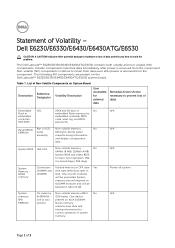
... Power off system N/A Page 1 of LCD Non-volatile memory No EEPROM panel 64K bytes. The Dell Latitude™ E6230/E6330/E6430/E6430ATG/E6530 contains both modules will be populated. Table 1. Panel EEDID Part of 3 System...boot operation, PSA (on System Board Reference Description Volatility Description Designator User Accessible for external data Remedial Action (Action necessary to hardware or loss of system memory. Stores panel assembly manufacturing information and display configuration data. One device one or two present on the Dell Latitude™ E6230...
... Power off system N/A Page 1 of LCD Non-volatile memory No EEPROM panel 64K bytes. The Dell Latitude™ E6230/E6330/E6430/E6430ATG/E6530 contains both modules will be populated. Table 1. Panel EEDID Part of 3 System...boot operation, PSA (on System Board Reference Description Volatility Description Designator User Accessible for external data Remedial Action (Action necessary to hardware or loss of system memory. Stores panel assembly manufacturing information and display configuration data. One device one or two present on the Dell Latitude™ E6230...
Statement of Volatility
Page 3
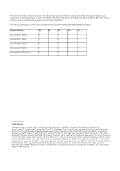
... does not save any component on which clears all the states supported by Dell Latitude™ E6230/E6330/E6430/E6430ATG/E6530 Model Number Dell Latitude™ E6230 Dell Latitude™ E6330 Dell Latitude™ E6430 Dell Latitude™ E6530 Dell Latitude™ E6430 ATG S0 S1 S3 S4 S5 X X X X X X X X X X X X X X X X X X X X © 2012 Dell Inc. in any context to wake up the system. The following table shows...
... does not save any component on which clears all the states supported by Dell Latitude™ E6230/E6330/E6430/E6430ATG/E6530 Model Number Dell Latitude™ E6230 Dell Latitude™ E6330 Dell Latitude™ E6430 Dell Latitude™ E6530 Dell Latitude™ E6430 ATG S0 S1 S3 S4 S5 X X X X X X X X X X X X X X X X X X X X © 2012 Dell Inc. in any context to wake up the system. The following table shows...


