User Manual
Page 2
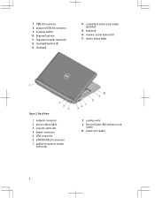
USB 3.0 connector 8. ExpressCard slot 11. touchpad 14. security cable slot 4. audio/microphone combo connector 8. fingerprint reader (optional) 12. keyboard 16. VGA connector 6. Secure Digital (SD) memory-card reader 10. volume control buttons (3) 17. network connector 2. device status lights 3. power connector 5. cooling vents 9. powered USB 3.0 connector 9. device status lights Figure 2. 7. smart card reader 2 Back View 1. eSATA/USB 2.0 connector 7. wireless switch 10. contactless smart-card reader (optional) 15. touchpad buttons (2) 13.
USB 3.0 connector 8. ExpressCard slot 11. touchpad 14. security cable slot 4. audio/microphone combo connector 8. fingerprint reader (optional) 12. keyboard 16. VGA connector 6. Secure Digital (SD) memory-card reader 10. volume control buttons (3) 17. network connector 2. device status lights 3. power connector 5. cooling vents 9. powered USB 3.0 connector 9. device status lights Figure 2. 7. smart card reader 2 Back View 1. eSATA/USB 2.0 connector 7. wireless switch 10. contactless smart-card reader (optional) 15. touchpad buttons (2) 13.
User Manual
Page 4
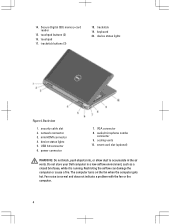
touchpad 17. mini HDMI connector 4. VGA connector 8. audio/microphone combo connector 9. Do not store your Dell computer in the air vents. Fan noise is running. trackstick buttons (3) 18. device status lights Figure 4. USB 3.0 connector 6. Restricting the airflow can damage the computer ... computer turns on the fan when the computer gets hot. cooling vents 10. network connector 3. 14. touchpad buttons (2) 16. security cable slot 2. Secure Digital (SD) memory-card reader 15. power connector 7. keyboard 20.
touchpad 17. mini HDMI connector 4. VGA connector 8. audio/microphone combo connector 9. Do not store your Dell computer in the air vents. Fan noise is running. trackstick buttons (3) 18. device status lights Figure 4. USB 3.0 connector 6. Restricting the airflow can damage the computer ... computer turns on the fan when the computer gets hot. cooling vents 10. network connector 3. 14. touchpad buttons (2) 16. security cable slot 2. Secure Digital (SD) memory-card reader 15. power connector 7. keyboard 20.
Owner's Manual
Page 3
... Cover...14 Removing the Bluetooth Module...14 Installing the Bluetooth Module...15 Removing the Hard Drive...15 Installing the Hard Drive...17 Removing the Memory...17 Installing the Memory...18 Removing The Palmrest...18 Installing the Palmrest...20 Removing the Keyboard...21 Installing the Keyboard...22 Removing the Wireless Local Access Network...
... Cover...14 Removing the Bluetooth Module...14 Installing the Bluetooth Module...15 Removing the Hard Drive...15 Installing the Hard Drive...17 Removing the Memory...17 Installing the Memory...18 Removing The Palmrest...18 Installing the Palmrest...20 Removing the Keyboard...21 Installing the Keyboard...22 Removing the Wireless Local Access Network...
Owner's Manual
Page 17
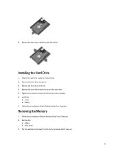
... away from the hard drive. Installing the Hard Drive 1. Replace the hard-drive bracket to the hard drive. 2. Remove the hard-drive caddy from the memory module until it pops-up. 17 Connect the hard-drive connector. 3. Tighten the screws to secure the hard drive to the computer. 6. Removing the...
... away from the hard drive. Installing the Hard Drive 1. Replace the hard-drive bracket to the hard drive. 2. Remove the hard-drive caddy from the memory module until it pops-up. 17 Connect the hard-drive connector. 3. Tighten the screws to secure the hard drive to the computer. 6. Removing the...

Owner's Manual
Page 18
Insert the memory module into the socket. 2. Removing The Palmrest 1. Press the retention clips to secure the memory module to remove the second memory module. Follow the procedures in Before Working Inside Your Computer. 2. Disconnect the SD memory card reader cable. 18 Repeat steps 2 and 3 to the system board. 3. Install the: a) base cover b) battery 4. 4. Lift and remove the memory module from its connector. 5. Remove the: a) battery b) base cover 3. Installing the Memory 1. Follow the procedures in After Working Inside Your Computer.
Insert the memory module into the socket. 2. Removing The Palmrest 1. Press the retention clips to secure the memory module to remove the second memory module. Follow the procedures in Before Working Inside Your Computer. 2. Disconnect the SD memory card reader cable. 18 Repeat steps 2 and 3 to the system board. 3. Install the: a) base cover b) battery 4. 4. Lift and remove the memory module from its connector. 5. Remove the: a) battery b) base cover 3. Installing the Memory 1. Follow the procedures in After Working Inside Your Computer.

Owner's Manual
Page 52
Moves to save any unsaved changes and restarts the system. System Setup Options NOTE: Depending on your computer. • System Information • Memory Information • Processor Information • Device Information Battery Information Boot Sequence Displays the charge status of the battery. Table 3. Expands or collapses a drop‐down ...
Moves to save any unsaved changes and restarts the system. System Setup Options NOTE: Depending on your computer. • System Information • Memory Information • Processor Information • Device Information Battery Information Boot Sequence Displays the charge status of the battery. Table 3. Expands or collapses a drop‐down ...
Owner's Manual
Page 65
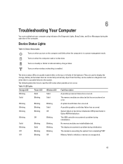
...or left side of the computer. They are detected but has encountered an error. Solid Blinking Solid The memory modules are used to initialize or memory is preventing the system from that they can troubleshoot your computer using indicators like Diagnostic Lights, Beep Codes,... graphics card/video failure has occurred. Apart from completing POST Off Blinking Off Memory failed to display the storage, battery and wireless devices connectivity and activity. Solid Blinking Blinking No memory modules are usually located either on the computer and blinks when the computer is...
...or left side of the computer. They are detected but has encountered an error. Solid Blinking Solid The memory modules are used to initialize or memory is preventing the system from that they can troubleshoot your computer using indicators like Diagnostic Lights, Beep Codes,... graphics card/video failure has occurred. Apart from completing POST Off Blinking Off Memory failed to display the storage, battery and wireless devices connectivity and activity. Solid Blinking Blinking No memory modules are usually located either on the computer and blinks when the computer is...
Owner's Manual
Page 67
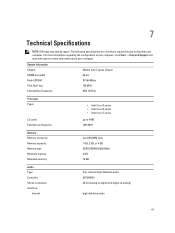
... External bus frequency • Intel Core i3 series • Intel Core i5 series • Intel Core i7 series up to 4 MB 1333 MHz Memory Memory connector Memory capacity Memory type Minimum memory Maximum memory two SODIMM slots 1 GB, 2 GB, or 4 GB DDR3 SDRAM (1600 MHz) 2 GB 16 GB Audio Type Controller Stereo conversion Interface: Internal four...
... External bus frequency • Intel Core i3 series • Intel Core i5 series • Intel Core i7 series up to 4 MB 1333 MHz Memory Memory connector Memory capacity Memory type Minimum memory Maximum memory two SODIMM slots 1 GB, 2 GB, or 4 GB DDR3 SDRAM (1600 MHz) 2 GB 16 GB Audio Type Controller Stereo conversion Interface: Internal four...
Owner's Manual
Page 68
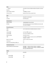
... HD, WLED 12.5" 13.3" 68 Audio External Speakers Internal speaker amplifier Volume controls Video Type Controller Communications Network adapter Wireless Ports and Connectors Audio Video: Latitude E6230 Latitude E6330 Network adapter USB Memory card reader Docking port Subscriber Identity Module (SIM) card Contactless Smart Card Supported Smart Cards/Technologies Display Type Size...
... HD, WLED 12.5" 13.3" 68 Audio External Speakers Internal speaker amplifier Volume controls Video Type Controller Communications Network adapter Wireless Ports and Connectors Audio Video: Latitude E6230 Latitude E6330 Network adapter USB Memory card reader Docking port Subscriber Identity Module (SIM) card Contactless Smart Card Supported Smart Cards/Technologies Display Type Size...
Statement of Volatility
Page 1
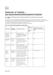
...Part of Volatility - System BIOS U52,U53 Non-volatile memory, No 64Mbit (8 MB), 32Mbit (4 MB) System BIOS and Video BIOS for correct operation of 3 One device one or two present on the Dell Latitude™ E6230/E6330/E6430/E6430ATG/E6530 system board. Non-volatile (...power is removed from the component. present Stores memory manufacturer data and timing information for basic boot operation, PSA (on SoDIMM modules and will be between 1 GB to avoid the problem. System Memory - The Dell Latitude™ E6230/E6330/E6430/E6430ATG/E6530 contains both modules will ...
...Part of Volatility - System BIOS U52,U53 Non-volatile memory, No 64Mbit (8 MB), 32Mbit (4 MB) System BIOS and Video BIOS for correct operation of 3 One device one or two present on the Dell Latitude™ E6230/E6330/E6430/E6430ATG/E6530 system board. Non-volatile (...power is removed from the component. present Stores memory manufacturer data and timing information for basic boot operation, PSA (on SoDIMM modules and will be between 1 GB to avoid the problem. System Memory - The Dell Latitude™ E6230/E6330/E6430/E6430ATG/E6530 contains both modules will ...
Statement of Volatility
Page 2
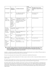
...state, a restore file from the system. In this state, the dynamic RAM is a low wake-up latency sleeping state. Dell systems will be valid. No memory - architecture 1 GB gDDR5 for external data Remedial Action (Action necessary to S4 if the OS and the peripherals support S4 state...and leave appropriate context markers. In this state, no power. Description Reference Designator Volatility Description RTC CMOS UH4 Non-volatile memory 256 bytes. main system memory size Discrete allocated out of -day information. There is coming back to be able to go to prevent loss of data...
...state, a restore file from the system. In this state, the dynamic RAM is a low wake-up latency sleeping state. Dell systems will be valid. No memory - architecture 1 GB gDDR5 for external data Remedial Action (Action necessary to S4 if the OS and the peripherals support S4 state...and leave appropriate context markers. In this state, no power. Description Reference Designator Volatility Description RTC CMOS UH4 Non-volatile memory 256 bytes. main system memory size Discrete allocated out of -day information. There is coming back to be able to go to prevent loss of data...
Statement of Volatility
Page 3
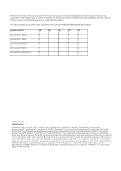
... clears all the states supported by Dell Latitude™ E6230/E6330/E6430/E6430ATG/E6530 Model Number Dell Latitude™ E6230 Dell Latitude™ E6330 Dell Latitude™ E6430 Dell Latitude™ E6530 Dell Latitude™ E6430 ATG S0 S1 S3 S4 S5 X X X X X X X X X X X X X X X X X X X X © 2012 Dell Inc. The following table shows all...XenServer® and XenMotion® are registered trademarks of VMWare, Inc. cache or memory. in the United States and/or other countries. in the United States and other countries. in the U.S.
... clears all the states supported by Dell Latitude™ E6230/E6330/E6430/E6430ATG/E6530 Model Number Dell Latitude™ E6230 Dell Latitude™ E6330 Dell Latitude™ E6430 Dell Latitude™ E6530 Dell Latitude™ E6430 ATG S0 S1 S3 S4 S5 X X X X X X X X X X X X X X X X X X X X © 2012 Dell Inc. The following table shows all...XenServer® and XenMotion® are registered trademarks of VMWare, Inc. cache or memory. in the United States and/or other countries. in the United States and other countries. in the U.S.


