Owner's Manual
Page 3
... Cover...13 Installing the Base Cover...14 Removing the Bluetooth Module...14 Installing the Bluetooth Module...15 Removing the Hard Drive...15 Installing the Hard Drive...17 Removing the Memory...17 Installing the Memory...18 Removing The Palmrest...18 Installing the Palmrest...20 Removing the Keyboard...21 Installing the Keyboard...22 Removing the Wireless Local Access Network (WLAN...
... Cover...13 Installing the Base Cover...14 Removing the Bluetooth Module...14 Installing the Bluetooth Module...15 Removing the Hard Drive...15 Installing the Hard Drive...17 Removing the Memory...17 Installing the Memory...18 Removing The Palmrest...18 Installing the Palmrest...20 Removing the Keyboard...21 Installing the Keyboard...22 Removing the Wireless Local Access Network (WLAN...
Owner's Manual
Page 21
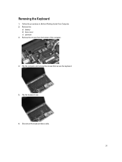
Removing the Keyboard 1. Flip the computer and remove the screws that secure the keyboard. 5. Disconnect the keyboard data cable. 21 Remove the screws from the bottom of the computer. 4. Flip the keyboard over. 6. Remove the: a) battery b) base cover c) palmrest 3. Follow the procedures in Before Working Inside Your Computer. 2.
Removing the Keyboard 1. Flip the computer and remove the screws that secure the keyboard. 5. Disconnect the keyboard data cable. 21 Remove the screws from the bottom of the computer. 4. Flip the keyboard over. 6. Remove the: a) battery b) base cover c) palmrest 3. Follow the procedures in Before Working Inside Your Computer. 2.
Owner's Manual
Page 22
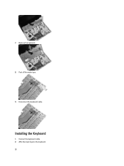
Remove the keyboard. 8. Disconnect the keyboard cable. Connect the keyboard cable. 2. Affix the mylar tape to the keyboard. 22 7. Installing the Keyboard 1. Peel off the mylar tape. 9.
Remove the keyboard. 8. Disconnect the keyboard cable. Connect the keyboard cable. 2. Affix the mylar tape to the keyboard. 22 7. Installing the Keyboard 1. Peel off the mylar tape. 9.
Owner's Manual
Page 23
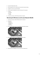
...of the computer. 7. Follow the procedures in After Working Inside Your Computer. Remove the: a) SD Card b) ExpressCard c) battery d) base cover 3. Slide the keyboard into place. 5. Remove the screw that it upwards. 4. Slide and remove the WLAN card out from the WLAN card by pulling it snaps into ...palmrest b) cover c) battery 8. Disconnect the antenna cables from its compartment and ensure that secures the WLAN card to secure the keyboard. 6. Follow the procedures in Before Working Inside Your Computer. 2. Removing the Wireless Local Access Network (WLAN) 1. Connect the...
...of the computer. 7. Follow the procedures in After Working Inside Your Computer. Remove the: a) SD Card b) ExpressCard c) battery d) base cover 3. Slide the keyboard into place. 5. Remove the screw that it upwards. 4. Slide and remove the WLAN card out from the WLAN card by pulling it snaps into ...palmrest b) cover c) battery 8. Disconnect the antenna cables from its compartment and ensure that secures the WLAN card to secure the keyboard. 6. Follow the procedures in Before Working Inside Your Computer. 2. Removing the Wireless Local Access Network (WLAN) 1. Connect the...

Owner's Manual
Page 28
... the procedures in After Working Inside Your Computer. Installing the Speakers 1. Install the: a) base cover b) battery c) ExpressCard d) SD card 4. Removing the Chassis Base 1. Remove the: a) SD card b) ExpressCard c) battery d) base cover e) palmrest f) keyboard g) bluetooth module h) heat-sink fan i) speakers 3. Follow the procedures in Before Working Inside Your Computer. 2. Tighten the screws to secure...
... the procedures in After Working Inside Your Computer. Installing the Speakers 1. Install the: a) base cover b) battery c) ExpressCard d) SD card 4. Removing the Chassis Base 1. Remove the: a) SD card b) ExpressCard c) battery d) base cover e) palmrest f) keyboard g) bluetooth module h) heat-sink fan i) speakers 3. Follow the procedures in Before Working Inside Your Computer. 2. Tighten the screws to secure...
Owner's Manual
Page 29
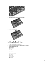
Connect the following cables: a) hall sensor b) touchpad 4. Install the: a) speakers b) heat-sink fan c) bluetooth module d) keyboard e) palmrest f) base cover g) battery 29 Pull up the chassis base. Installing the Chassis Base 1. Align the chassis base to the computer. 3. 5. Tighten the screws to secure the chassis base to the computer. 2. Remove the screws that secure the chassis base. 6.
Connect the following cables: a) hall sensor b) touchpad 4. Install the: a) speakers b) heat-sink fan c) bluetooth module d) keyboard e) palmrest f) base cover g) battery 29 Pull up the chassis base. Installing the Chassis Base 1. Align the chassis base to the computer. 3. 5. Tighten the screws to secure the chassis base to the computer. 2. Remove the screws that secure the chassis base. 6.
Owner's Manual
Page 30
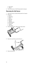
Remove the: a) SD card b) ExpressCard c) battery d) base cover e) palmrest f) keyboard g) bluetooth module h) heat-sink fan i) speakers j) base chassis 3. Unthread the hall sensor cable from the routing channel. 4. Remove the hall sensor. 30 Follow the procedures in After Working Inside Your Computer. Remove the screw that secures the hall sensor. 5. Follow the procedures in Before Working Inside Your Computer. 2. h) ExpressCard i) SD card 5. Removing the Hall Sensor 1.
Remove the: a) SD card b) ExpressCard c) battery d) base cover e) palmrest f) keyboard g) bluetooth module h) heat-sink fan i) speakers j) base chassis 3. Unthread the hall sensor cable from the routing channel. 4. Remove the hall sensor. 30 Follow the procedures in After Working Inside Your Computer. Remove the screw that secures the hall sensor. 5. Follow the procedures in Before Working Inside Your Computer. 2. h) ExpressCard i) SD card 5. Removing the Hall Sensor 1.
Owner's Manual
Page 31
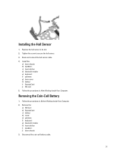
Install the: a) base chassis b) speakers c) heat-sink fan d) bluetooth module e) keyboard f) palmrest g) base cover h) battery i) ExpressCard j) SD card 5. Remove the: a) SD Card b) ExpressCard c) battery d) cover e) palmrest f) keyboard g) bluetooth module h) heat-sink fan i) speakers j) base chassis 3. Disconnect the coin-cell battery cable. 31 Route and connect the hall sensor cable. 4. Follow the procedures ...
Install the: a) base chassis b) speakers c) heat-sink fan d) bluetooth module e) keyboard f) palmrest g) base cover h) battery i) ExpressCard j) SD card 5. Remove the: a) SD Card b) ExpressCard c) battery d) cover e) palmrest f) keyboard g) bluetooth module h) heat-sink fan i) speakers j) base chassis 3. Disconnect the coin-cell battery cable. 31 Route and connect the hall sensor cable. 4. Follow the procedures ...
Owner's Manual
Page 32
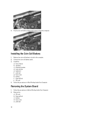
Install the: a) base chassis b) speakers c) bluetooth module d) heat-sink fan e) keyboard f) palmrest g) base cover h) battery i) ExpressCard j) SD card 4. Remove the: a) SD card b) ExpressCard c) battery d) base cover e) palmrest 32 Connect the coin-cell battery cable. 3. Replace the coin-...cell battery in its slot in After Working Inside Your Computer. Installing the Coin-Cell Battery 1. Removing the System Board 1. Follow the procedures in the computer. 2. Follow the procedures in Before Working Inside Your Computer. 2. Pry the coin...
Install the: a) base chassis b) speakers c) bluetooth module d) heat-sink fan e) keyboard f) palmrest g) base cover h) battery i) ExpressCard j) SD card 4. Remove the: a) SD card b) ExpressCard c) battery d) base cover e) palmrest 32 Connect the coin-cell battery cable. 3. Replace the coin-...cell battery in its slot in After Working Inside Your Computer. Installing the Coin-Cell Battery 1. Removing the System Board 1. Follow the procedures in the computer. 2. Follow the procedures in Before Working Inside Your Computer. 2. Pry the coin...
Owner's Manual
Page 33
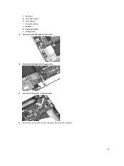
Disconnect the WiFi-switch board cable. 4. Disconnect the ExpressCard cage cable. 5. Disconnect the power-connector cable. 6. Remove the screws that secure the system board to the computer. 33 f) keyboard g) bluetooth module h) heat-sink fan i) heat sink module j) speakers k) display assembly l) chassis base 3.
Disconnect the WiFi-switch board cable. 4. Disconnect the ExpressCard cage cable. 5. Disconnect the power-connector cable. 6. Remove the screws that secure the system board to the computer. 33 f) keyboard g) bluetooth module h) heat-sink fan i) heat sink module j) speakers k) display assembly l) chassis base 3.
Owner's Manual
Page 35
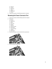
Disconnect the power-connector cable from the system board. 4. Follow the procedures in Before Working Inside Your Computer. 2. Follow the procedures in After Working Inside Your Computer. Removing the Power-Connector Port 1. g) keyboard h) palmrest i) base cover j) battery k) ExpressCard l) SD card 5. Remove the: a) SD card b) ExpressCard c) battery d) base cover e) palmrest f) keyboard g) bluetooth module h) heat-sink fan i) heat-sink module j) speakers k) base chassis 3. Remove the power connector port. 35
Disconnect the power-connector cable from the system board. 4. Follow the procedures in Before Working Inside Your Computer. 2. Follow the procedures in After Working Inside Your Computer. Removing the Power-Connector Port 1. g) keyboard h) palmrest i) base cover j) battery k) ExpressCard l) SD card 5. Remove the: a) SD card b) ExpressCard c) battery d) base cover e) palmrest f) keyboard g) bluetooth module h) heat-sink fan i) heat-sink module j) speakers k) base chassis 3. Remove the power connector port. 35

Owner's Manual
Page 36
... Your Computer. Install the: a) base chassis b) speakers c) heat-sink module d) heat-sink fan e) bluetooth module f) keyboard g) palmrest h) base cover i) battery j) ExpressCard k) SD card 4. Removing the ExpressCard Cage 1. Disconnect the ExpressCard reader cable. 4. Remove the: a) SD card b) ExpressCard c) battery d) base cover e) palmrest f) keyboard g) bluetooth module h) heat sink i) speakers j) base chassis 3. Installing the Power-Connector Port...
... Your Computer. Install the: a) base chassis b) speakers c) heat-sink module d) heat-sink fan e) bluetooth module f) keyboard g) palmrest h) base cover i) battery j) ExpressCard k) SD card 4. Removing the ExpressCard Cage 1. Disconnect the ExpressCard reader cable. 4. Remove the: a) SD card b) ExpressCard c) battery d) base cover e) palmrest f) keyboard g) bluetooth module h) heat sink i) speakers j) base chassis 3. Installing the Power-Connector Port...

Owner's Manual
Page 37
... the computer 3. Connect the ExpressCard reader cable. 4. Follow the procedures in After Working Inside Your Computer. Remove the ExpressCard cage. Follow the procedures in Before Working Inside Your Computer. 2. Install the: a) base chassis b) speakers c) heatsink d) bluetooth module e) keyboard f) palmrest g) base cover h) battery i) ExpressCard j) SD card 5. Insert the ExpressCard cage into its compartment...
... the computer 3. Connect the ExpressCard reader cable. 4. Follow the procedures in After Working Inside Your Computer. Remove the ExpressCard cage. Follow the procedures in Before Working Inside Your Computer. 2. Install the: a) base chassis b) speakers c) heatsink d) bluetooth module e) keyboard f) palmrest g) base cover h) battery i) ExpressCard j) SD card 5. Insert the ExpressCard cage into its compartment...
Owner's Manual
Page 38
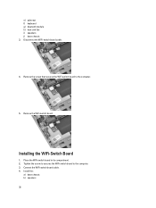
Remove the screw that secures the WiFi-switch board to the computer. 3. Connect the WiFi-switch board cable. 4. Place the WiFi-switch board in its compartment. 2. Disconnect the WiFi-switch board cable. 4. Installing the WiFi-Switch Board 1. Tighten the screw to secures the WiFi-switch board to the computer. 5. Install the: a) base chassis b) speakers 38 e) palmrest f) keyboard g) bluetooth module h) heat-sink fan i) speakers j) base chassis 3. Remove the WiFi-switch board.
Remove the screw that secures the WiFi-switch board to the computer. 3. Connect the WiFi-switch board cable. 4. Place the WiFi-switch board in its compartment. 2. Disconnect the WiFi-switch board cable. 4. Installing the WiFi-Switch Board 1. Tighten the screw to secures the WiFi-switch board to the computer. 5. Install the: a) base chassis b) speakers 38 e) palmrest f) keyboard g) bluetooth module h) heat-sink fan i) speakers j) base chassis 3. Remove the WiFi-switch board.
Owner's Manual
Page 39
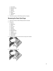
Removing the Smart Card Cage 1. Remove the: a) SD card b) ExpressCard c) battery d) base cover e) palmrest f) keyboard g) heat-sink fan h) bluetooth module i) speakers j) display assembly k) lower chassis l) system board 3. Follow the procedures in After Working Inside Your Computer. c) heat-sink fan d) bluetooth module e) keyboard f) palmrest g) base cover h) battery i) ExpressCard j) SD card 5. Remove the smart card cage. 39 Remove the screw that secures the smart card cage to the computer. 4. Follow the procedures in Before Working Inside Your Computer. 2.
Removing the Smart Card Cage 1. Remove the: a) SD card b) ExpressCard c) battery d) base cover e) palmrest f) keyboard g) heat-sink fan h) bluetooth module i) speakers j) display assembly k) lower chassis l) system board 3. Follow the procedures in After Working Inside Your Computer. c) heat-sink fan d) bluetooth module e) keyboard f) palmrest g) base cover h) battery i) ExpressCard j) SD card 5. Remove the smart card cage. 39 Remove the screw that secures the smart card cage to the computer. 4. Follow the procedures in Before Working Inside Your Computer. 2.
Owner's Manual
Page 40
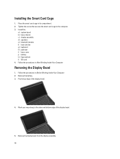
...1. Place the smart card cage in After Working Inside Your Computer. Remove the battery. 3. Tighten the screw that secures the smart card cage to the sides and bottom edge of the display bezel. 4. Removing the Display Bezel 1. Follow the procedures in its compartment. 2. Work ...your way along to the computer. 3. Follow the procedures in Before Working Inside Your Computer. 2. Remove the display bezel from the display assembly. 40 Pry the top edge of the display bezel. 5. Install the: a) system board b) base chassis c)...
...1. Place the smart card cage in After Working Inside Your Computer. Remove the battery. 3. Tighten the screw that secures the smart card cage to the sides and bottom edge of the display bezel. 4. Removing the Display Bezel 1. Follow the procedures in its compartment. 2. Work ...your way along to the computer. 3. Follow the procedures in Before Working Inside Your Computer. 2. Remove the display bezel from the display assembly. 40 Pry the top edge of the display bezel. 5. Install the: a) system board b) base chassis c)...
Owner's Manual
Page 42
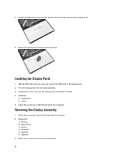
... display assembly. Place the display panel onto the display assembly. 3. Follow the procedures in Before Working Inside Your Computer. 2. Remove the display panel from the display panel. 6. Installing the Display Panel 1. Tighten the screws that secure the display panel to the... display panel. 2. Follow the procedures in After Working Inside Your Computer. Remove the: a) SD Card b) ExpressCard c) battery d) base cover e) palmrest f) keyboard 3. Install the: a) display bezel b) battery 5. Affix the LVDS cable connector tape and connect the LVDS...
... display assembly. Place the display panel onto the display assembly. 3. Follow the procedures in Before Working Inside Your Computer. 2. Remove the display panel from the display panel. 6. Installing the Display Panel 1. Tighten the screws that secure the display panel to the... display panel. 2. Follow the procedures in After Working Inside Your Computer. Remove the: a) SD Card b) ExpressCard c) battery d) base cover e) palmrest f) keyboard 3. Install the: a) display bezel b) battery 5. Affix the LVDS cable connector tape and connect the LVDS...
Owner's Manual
Page 45
...procedures in its slot. 7. Peel away the conductive tape. 4. Remove the screw that are connected to the computer. 8. Route the antenna cables through the routing channel. 4. Connect the antenna cables to the display assembly. 5. Remove the: a) battery b) display bezel 3. Route and connect the ...LVDS cable. 6. Flip the computer and tighten the screws at the bottom. 10. Removing the Camera 1. Tighten the screws to secure the LVDS bracket to the wireless solutions. 9. Install the: a) keyboard b) palmrest c) base cover d) battery e) ExpressCard f) SD card 11. Follow the ...
...procedures in its slot. 7. Peel away the conductive tape. 4. Remove the screw that are connected to the computer. 8. Route the antenna cables through the routing channel. 4. Connect the antenna cables to the display assembly. 5. Remove the: a) battery b) display bezel 3. Route and connect the ...LVDS cable. 6. Flip the computer and tighten the screws at the bottom. 10. Removing the Camera 1. Tighten the screws to secure the LVDS bracket to the wireless solutions. 9. Install the: a) keyboard b) palmrest c) base cover d) battery e) ExpressCard f) SD card 11. Follow the ...
Owner's Manual
Page 47
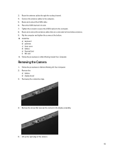
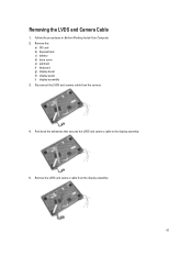
Disconnect the LVDS and camera cable from the display assembly. 47 Peel back the adhesives that secures the LVDS and camera cable to the display assembly. 5. Follow the procedures in Before Working Inside Your Computer. 2. Remove the LVDS and camera cable from the camera. 4. Removing the LVDS and Camera Cable 1. Remove the: a) SD card b) ExpressCard c) battery d) base cover e) palmrest f) keyboard g) display bezel h) display panel i) display assembly 3.
Disconnect the LVDS and camera cable from the display assembly. 47 Peel back the adhesives that secures the LVDS and camera cable to the display assembly. 5. Follow the procedures in Before Working Inside Your Computer. 2. Remove the LVDS and camera cable from the camera. 4. Removing the LVDS and Camera Cable 1. Remove the: a) SD card b) ExpressCard c) battery d) base cover e) palmrest f) keyboard g) display bezel h) display panel i) display assembly 3.


