Owner's Manual
Page 3
... Base Cover...13 Installing the Base Cover...14 Removing the Bluetooth Module...14 Installing the Bluetooth Module...15 Removing the Hard Drive...15 Installing the Hard Drive...17 Removing the Memory...17 Installing the Memory...18 Removing The Palmrest...18 Installing the Palmrest...20 Removing the Keyboard...21 Installing the Keyboard...22 Removing the Wireless Local Access Network (WLAN 23...
... Base Cover...13 Installing the Base Cover...14 Removing the Bluetooth Module...14 Installing the Bluetooth Module...15 Removing the Hard Drive...15 Installing the Hard Drive...17 Removing the Memory...17 Installing the Memory...18 Removing The Palmrest...18 Installing the Palmrest...20 Removing the Keyboard...21 Installing the Keyboard...22 Removing the Wireless Local Access Network (WLAN 23...

Owner's Manual
Page 15
... the bluetooth cable to the computer. 3. Removing the Hard Drive 1. Remove the: a) battery b) base cover 3. 4. Remove the screw that secure the hard drive to the computer. 5. Follow the procedures in After Working Inside Your Computer. Installing the Bluetooth Module 1. Tighten the screw to secure the bluetooth module to its connector. 2. Remove the screws that secures the bluetooth module...
... the bluetooth cable to the computer. 3. Removing the Hard Drive 1. Remove the: a) battery b) base cover 3. 4. Remove the screw that secure the hard drive to the computer. 5. Follow the procedures in After Working Inside Your Computer. Installing the Bluetooth Module 1. Tighten the screw to secure the bluetooth module to its connector. 2. Remove the screws that secures the bluetooth module...
Owner's Manual
Page 16
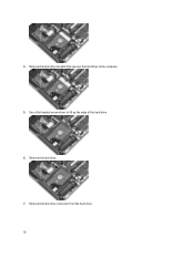
Remove the hard-drive connector from the hard drive. 16 Remove the hard drive. 7. Use a flat-headed screw driver to the computer. 5. 4. Remove the hard-drive bracket that secures the hard drive to lift up the edge of the hard drive. 6.
Remove the hard-drive connector from the hard drive. 16 Remove the hard drive. 7. Use a flat-headed screw driver to the computer. 5. 4. Remove the hard-drive bracket that secures the hard drive to lift up the edge of the hard drive. 6.
Owner's Manual
Page 17
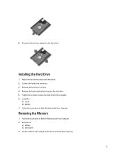
Follow the procedures in Before Working Inside Your Computer. 2. Connect the hard-drive connector. 3. Replace the hard-drive bracket to the hard drive. 2. Removing the Memory 1. Installing the Hard Drive 1. Remove the: a) battery b) base cover 3. 8. Attach the hard-drive caddy to secure the hard drive. 5. Remove the hard-drive caddy from the memory module until it pops-up. 17 Install the: a) cover b) battery 7. Tighten the screws to secure...
Follow the procedures in Before Working Inside Your Computer. 2. Connect the hard-drive connector. 3. Replace the hard-drive bracket to the hard drive. 2. Removing the Memory 1. Installing the Hard Drive 1. Remove the: a) battery b) base cover 3. 8. Attach the hard-drive caddy to secure the hard drive. 5. Remove the hard-drive caddy from the memory module until it pops-up. 17 Install the: a) cover b) battery 7. Tighten the screws to secure...
Owner's Manual
Page 51
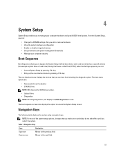
...‐defined boot device order and boot directly to a specific device (for example: optical drive or hard drive). From the System Setup, you can: • Change the NVRAM settings after you add or remove hardware • View the system hardware configuration • Enable or disable integrated devices •...previous field. Navigation Keys The following table displays the system setup navigation keys. During the Power-on Self Test (POST), when the Dell logo appears, you can boot from including the diagnostic option. The boot-menu options are recorded but do not take effect until you...
...‐defined boot device order and boot directly to a specific device (for example: optical drive or hard drive). From the System Setup, you can: • Change the NVRAM settings after you add or remove hardware • View the system hardware configuration • Enable or disable integrated devices •...previous field. Navigation Keys The following table displays the system setup navigation keys. During the Power-on Self Test (POST), when the Dell logo appears, you can boot from including the diagnostic option. The boot-menu options are recorded but do not take effect until you...
Statement of Volatility
Page 2
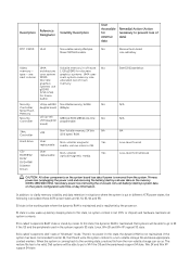
...uses system graphics systems. UMA uses next column DDR3. Security U4 (up latency sleeping state. Hard drive User Non-volatile magnetic Yes replaceable media, various sizes in off state. In this state, ... system board lose data if power is called "suspend to prevent loss of data) No Remove the on the system configuration and time-of main graphics memory. S1 state is the working...Controller U2 (up-sell USH Non Volatile memory, 16 Mbit No Controller daughter board) (2Mbyte). Dell systems will write the system context to be able to go to disk" state or "hibernate"...
...uses system graphics systems. UMA uses next column DDR3. Security U4 (up latency sleeping state. Hard drive User Non-volatile magnetic Yes replaceable media, various sizes in off state. In this state, ... system board lose data if power is called "suspend to prevent loss of data) No Remove the on the system configuration and time-of main graphics memory. S1 state is the working...Controller U2 (up-sell USH Non Volatile memory, 16 Mbit No Controller daughter board) (2Mbyte). Dell systems will write the system context to be able to go to disk" state or "hibernate"...


