Setup and Features Information Tech Sheet
Page 2
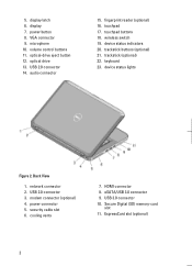
... 12. fingerprint reader (optional) 16. device status indicators 20. trackstick (optional) 22. USB 3.0 connector 10. 5. touchpad buttons 18. Back View 1. HDMI connector 8. display 7. microphone 10. keyboard 23. USB 2.0 connector 3. Secure Digital (SD) memory-card slot 11. ExpressCard slot (optional) 2 volume control buttons 11. optical drive 13. device status lights Figure 2. cooling...
... 12. fingerprint reader (optional) 16. device status indicators 20. trackstick (optional) 22. USB 3.0 connector 10. 5. touchpad buttons 18. Back View 1. HDMI connector 8. display 7. microphone 10. keyboard 23. USB 2.0 connector 3. Secure Digital (SD) memory-card slot 11. ExpressCard slot (optional) 2 volume control buttons 11. optical drive 13. device status lights Figure 2. cooling...
Setup and Features Information Tech Sheet
Page 4
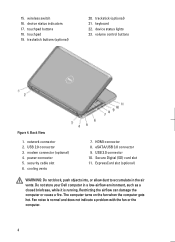
wireless switch 16. touchpad 19. Back View 1. modem connector (optional) 4. security cable slot 6. HDMI connector 8. Do not store your Dell computer in the air vents. touchpad buttons 18. network connector 2. eSATA/USB 3.0 connector 9. Restricting the airflow can damage the computer or cause a fire. 15. device ...) 21. USB 2.0 connector 3. USB 3.0 connector 10. The computer turns on the fan when the computer gets hot. volume control buttons Figure 4. Fan noise is running. keyboard 22. cooling vents 7. Secure Digital (SD) card slot 11.
wireless switch 16. touchpad 19. Back View 1. modem connector (optional) 4. security cable slot 6. HDMI connector 8. Do not store your Dell computer in the air vents. touchpad buttons 18. network connector 2. eSATA/USB 3.0 connector 9. Restricting the airflow can damage the computer or cause a fire. 15. device ...) 21. USB 2.0 connector 3. USB 3.0 connector 10. The computer turns on the fan when the computer gets hot. volume control buttons Figure 4. Fan noise is running. keyboard 22. cooling vents 7. Secure Digital (SD) card slot 11.
Setup and Features Information Tech Sheet
Page 5
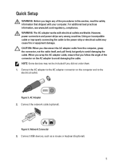
For additional best practices information, see www.dell.com/regulatory_compliance. When you wrap the AC adapter cable, ensure that shipped with electrical outlets worldwide. Figure 5. WARNING: The AC adapter works with your computer. ... and to the power strip or electrical outlet may not be included if you did not order them. 1. Connect USB devices, such as a mouse or keyboard (optional). 5
For additional best practices information, see www.dell.com/regulatory_compliance. When you wrap the AC adapter cable, ensure that shipped with electrical outlets worldwide. Figure 5. WARNING: The AC adapter works with your computer. ... and to the power strip or electrical outlet may not be included if you did not order them. 1. Connect USB devices, such as a mouse or keyboard (optional). 5
Statement of Volatility
Page 1
... memory, No 32 Mbit (4 MB), System BIOS and Video BIOS for correct operation of Non-Volatile Components on the Dell Latitude E5430/E5530 system board. Non-volatile (NV) components continue to four modules must be populated. List of system memory. Four SODIMM... connectors: JDIM1,2,3,4 Volatile memory in embedded controller MEC5035 192 KB of 2 N/A N/A Power off system N/A Page 1 of embedded Flash No memory for keyboard...
... memory, No 32 Mbit (4 MB), System BIOS and Video BIOS for correct operation of Non-Volatile Components on the Dell Latitude E5430/E5530 system board. Non-volatile (NV) components continue to four modules must be populated. List of system memory. Four SODIMM... connectors: JDIM1,2,3,4 Volatile memory in embedded controller MEC5035 192 KB of 2 N/A N/A Power off system N/A Page 1 of embedded Flash No memory for keyboard...
User Manual
Page 2
... Removing the Camera...10 Installing the Camera...10 Removing the Display Panel...10 Installing the Display Panel...12 Removing the Keyboard Trim...13 Installing the Keyboard Trim...14 Removing the Keyboard...14 Installing the Keyboard...17 Removing the Bottom Door...18 Installing the Bottom Door...19 Removing the Optical Drive...19 Installing the Optical...
... Removing the Camera...10 Installing the Camera...10 Removing the Display Panel...10 Installing the Display Panel...12 Removing the Keyboard Trim...13 Installing the Keyboard Trim...14 Removing the Keyboard...14 Installing the Keyboard...17 Removing the Bottom Door...18 Installing the Bottom Door...19 Removing the Optical Drive...19 Installing the Optical...

User Manual
Page 13
8. Removing the Keyboard Trim 1. Remove the battery. 3. Remove the screws at the back of the keyboard trim. 6. Work your way around the sides and the top edge of the computer. 4. Follow the procedures in After Working Inside Your Computer. Lift upwards and remove the keyboard trim from the bottom edge. 5. Pry up the keyboard trim starting from the computer. 13 Follow the procedures in Before Working Inside Your Computer. 2.
8. Removing the Keyboard Trim 1. Remove the battery. 3. Remove the screws at the back of the keyboard trim. 6. Work your way around the sides and the top edge of the computer. 4. Follow the procedures in After Working Inside Your Computer. Lift upwards and remove the keyboard trim from the bottom edge. 5. Pry up the keyboard trim starting from the computer. 13 Follow the procedures in Before Working Inside Your Computer. 2.

User Manual
Page 14
Align the keyboard trim to its compartment. 2. Press along the sides of the computer. 14 Removing the Keyboard 1. Follow the procedures in place. 3. Remove: a) battery b) keyboard trim 3. Remove the screw at the back of the keyboard trim until it snaps in Before Working Inside Your Computer. 2. Installing the Keyboard Trim 1. Install the battery. 4. Follow the procedures in After Working Inside Your Computer.
Align the keyboard trim to its compartment. 2. Press along the sides of the computer. 14 Removing the Keyboard 1. Follow the procedures in place. 3. Remove: a) battery b) keyboard trim 3. Remove the screw at the back of the keyboard trim until it snaps in Before Working Inside Your Computer. 2. Installing the Keyboard Trim 1. Install the battery. 4. Follow the procedures in After Working Inside Your Computer.

User Manual
Page 15
Remove the keyboard trim from the computer . Figure 9. 5. Lift the clip to release the keyboard trim from the computer . 15 Figure 8. 4.
Remove the keyboard trim from the computer . Figure 9. 5. Lift the clip to release the keyboard trim from the computer . 15 Figure 8. 4.
User Manual
Page 16
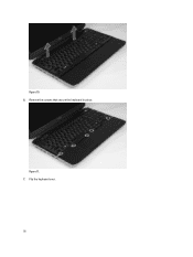
Figure 10. 6. Flip the keyboard over. 16 Remove the screws that secure the keyboard in place. Figure 11. 7.
Figure 10. 6. Flip the keyboard over. 16 Remove the screws that secure the keyboard in place. Figure 11. 7.

User Manual
Page 17
Affix the adhesive tape securing the keyboard flat flex cable to the back of the keyboard. 9. Peel off the adhesive tape securing the keyboard flat flex cable to the keyboard. 3. Installing the Keyboard 1. Fasten the keyboard cable clip. 17 Figure 13. Peel away the keyboard flat flex cable from the keyboard and remove it from the computer. Slide the keyboard into its compartment until all the metal tabs fit into their positions. 4. Figure 12. 8. Attach the keyboard flat flex cable to the keyboard. 2. Disconnect the keyboard flat flex cable. 10.
Affix the adhesive tape securing the keyboard flat flex cable to the back of the keyboard. 9. Peel off the adhesive tape securing the keyboard flat flex cable to the keyboard. 3. Installing the Keyboard 1. Fasten the keyboard cable clip. 17 Figure 13. Peel away the keyboard flat flex cable from the keyboard and remove it from the computer. Slide the keyboard into its compartment until all the metal tabs fit into their positions. 4. Figure 12. 8. Attach the keyboard flat flex cable to the keyboard. 2. Disconnect the keyboard flat flex cable. 10.

User Manual
Page 18
... b) battery 9. Follow the procedures in Before Working Inside Your Computer. 2. Removing the Bottom Door 1. Figure 14. 4. Press down on the keyboard to the palm rest. 7. 5. Install the screw at the back of the computer. 8. Slide and then lift the bottom door upwards and remove it from...the computer. 18 Remove the battery. 3. Remove the screws that all the snaps are fully engaged with the computer. 6. Install the screws that secure the keyboard to the left and right side ensuring that secure the bottom door. Follow the procedures in After Working Inside Your Computer.
... b) battery 9. Follow the procedures in Before Working Inside Your Computer. 2. Removing the Bottom Door 1. Figure 14. 4. Press down on the keyboard to the palm rest. 7. 5. Install the screw at the back of the computer. 8. Slide and then lift the bottom door upwards and remove it from...the computer. 18 Remove the battery. 3. Remove the screws that all the snaps are fully engaged with the computer. 6. Install the screws that secure the keyboard to the left and right side ensuring that secure the bottom door. Follow the procedures in After Working Inside Your Computer.
User Manual
Page 28
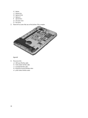
Disconnect the : a) LED board flat flex cable b) media button flat flex cable c) touchpad flat flex cable d) fingerprint scanner flat flex cable e) power button flat flex cable 28 Remove the screws that secure the bottom of the computer. Figure 27. 4. b) battery c) bottom door d) keyboard trim e) keyboard f) optical drive g) processor door h) hard drive 3.
Disconnect the : a) LED board flat flex cable b) media button flat flex cable c) touchpad flat flex cable d) fingerprint scanner flat flex cable e) power button flat flex cable 28 Remove the screws that secure the bottom of the computer. Figure 27. 4. b) battery c) bottom door d) keyboard trim e) keyboard f) optical drive g) processor door h) hard drive 3.
User Manual
Page 30
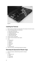
... Inside Your Computer. Follow the procedures in Before Working Inside Your Computer. 2. Install : a) processor door b) optical drive c) keyboard d) keyboard trim e) bottom door f) battery g) SD memory card 6. Figure 30. Remove: a) SD memory card b) battery c) access panel d) keyboard trim 30 Removing the ExpressCard Reader Cage 1. b) fingerprint scanner flat flex cable c) touchpad flat flex cable d) media...
... Inside Your Computer. Follow the procedures in Before Working Inside Your Computer. 2. Install : a) processor door b) optical drive c) keyboard d) keyboard trim e) bottom door f) battery g) SD memory card 6. Figure 30. Remove: a) SD memory card b) battery c) access panel d) keyboard trim 30 Removing the ExpressCard Reader Cage 1. b) fingerprint scanner flat flex cable c) touchpad flat flex cable d) media...
User Manual
Page 31
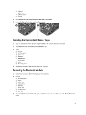
...procedures in the computer and snap it into place. 2. Remove: a) SD memory card b) battery c) bottom door d) keyboard trim e) keyboard f) optical drive g) processor door h) palm rest 3. Removing the Bluetooth Module 1. Remove the ExpressCard reader cage from the ... reader cage in After Working Inside Your Computer. Installing the ExpressCard Reader Cage 1. Install: a) palmrest b) right base panel c) optical drive d) keyboard e) keyboard trim f) access panel g) battery h) SD memory card 4. Follow the procedures in place. 4. Disconnect the Bluetooth cable from the computer. Remove...
...procedures in the computer and snap it into place. 2. Remove: a) SD memory card b) battery c) bottom door d) keyboard trim e) keyboard f) optical drive g) processor door h) palm rest 3. Removing the Bluetooth Module 1. Remove the ExpressCard reader cage from the ... reader cage in After Working Inside Your Computer. Installing the ExpressCard Reader Cage 1. Install: a) palmrest b) right base panel c) optical drive d) keyboard e) keyboard trim f) access panel g) battery h) SD memory card 4. Follow the procedures in place. 4. Disconnect the Bluetooth cable from the computer. Remove...
User Manual
Page 32
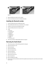
...Bluetooth module from the Bluetooth module. Installing the Bluetooth module 1. Connect the Bluetooth cable to the Bluetooth module. 2. Remove the keyboard trim. 6. Remove the optical drive. 8. Remove the SD memory card. 3. Disconnect the Bluetooth cable from the computer. 5..... 4. Follow the procedures in place. 32 Remove the Bluetooth module. 11. Install : a) palm rest b) processor door c) optical drive d) keyboard e) keyboard trim f) bottom door g) battery h) SD memory card 6. Remove the palmrest. 10. Install the screw that secures the audio board in Before ...
...Bluetooth module from the Bluetooth module. Installing the Bluetooth module 1. Connect the Bluetooth cable to the Bluetooth module. 2. Remove the keyboard trim. 6. Remove the optical drive. 8. Remove the SD memory card. 3. Disconnect the Bluetooth cable from the computer. 5..... 4. Follow the procedures in place. 32 Remove the Bluetooth module. 11. Install : a) palm rest b) processor door c) optical drive d) keyboard e) keyboard trim f) bottom door g) battery h) SD memory card 6. Remove the palmrest. 10. Install the screw that secures the audio board in Before ...
User Manual
Page 33
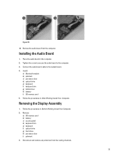
...in Before Working Inside Your Computer. 2. Installing the Audio Board 1. Install: a) Bluetooth module b) palmrest c) processor door d) optical drive e) keyboard f) keyboard trim g) bottom door h) battery i) SD memory card 5. Follow the procedures in After Working Inside Your Computer. Place the audio board in the... computer. 2. Remove: a) SD memory card b) battery c) access panel d) keyboard trim e) keyboard f) optical drive g) hard drive h) processor door i) palmrest 3. Remove the audio board from the routing channels. 33 Removing the ...
...in Before Working Inside Your Computer. 2. Installing the Audio Board 1. Install: a) Bluetooth module b) palmrest c) processor door d) optical drive e) keyboard f) keyboard trim g) bottom door h) battery i) SD memory card 5. Follow the procedures in After Working Inside Your Computer. Place the audio board in the... computer. 2. Remove: a) SD memory card b) battery c) access panel d) keyboard trim e) keyboard f) optical drive g) hard drive h) processor door i) palmrest 3. Remove the audio board from the routing channels. 33 Removing the ...
User Manual
Page 36
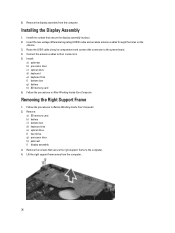
... right support frame away from the computer. Remove the display assembly from the computer. 36 Installing the Display Assembly 1. Install : a) palmrest b) processor door c) optical drive d) keyboard e) keyboard trim f) bottom door g) battery h) SD memory card 6. Remove: a) SD memory card b) battery c) bottom door...
... right support frame away from the computer. Remove the display assembly from the computer. 36 Installing the Display Assembly 1. Install : a) palmrest b) processor door c) optical drive d) keyboard e) keyboard trim f) bottom door g) battery h) SD memory card 6. Remove: a) SD memory card b) battery c) bottom door...
User Manual
Page 37
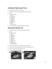
...on the back of the card. 5. Install: a) display assembly b) palmrest c) processor door d) hard drive e) optical drive f) keyboard g) keyboard trim h) bottom doorl i) battery j) SD memory card 4. Follow the procedures in After Working Inside Your Computer. Disconnect the RJ11...card. 6. Remove the screw that secures the modem card to the computer. 3. Remove: a) SD memory card b) battery c) bottom door d) keyboard trim e) keyboard f) optical drive g) hard drive h) processor door i) palmrest j) display assembly k) right support frame 3. Installing the Right Support Frame 1. Lift the...
...on the back of the card. 5. Install: a) display assembly b) palmrest c) processor door d) hard drive e) optical drive f) keyboard g) keyboard trim h) bottom doorl i) battery j) SD memory card 4. Follow the procedures in After Working Inside Your Computer. Disconnect the RJ11...card. 6. Remove the screw that secures the modem card to the computer. 3. Remove: a) SD memory card b) battery c) bottom door d) keyboard trim e) keyboard f) optical drive g) hard drive h) processor door i) palmrest j) display assembly k) right support frame 3. Installing the Right Support Frame 1. Lift the...
User Manual
Page 38
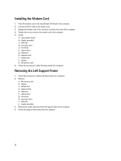
... to the computer. 4. Install: a) right support frame b) display assembly c) palmrest d) processor door e) hard drive f) optical drive g) keyboard h) keyboard trim i) bottom door j) battery k) SD memory card 6. Removing the Left Support Frame 1. Lift the left support frame to the computer...Your Computer. Follow the procedures in Before Working Inside Your Computer. 2. Remove: a) SD memory card b) battery c) bottom door d) keyboard trim e) keyboard f) optical drive g) hard drive h) processor door i) palmrest j) display assembly 3. Installing the Modem Card 1. Engage the modem card ...
... to the computer. 4. Install: a) right support frame b) display assembly c) palmrest d) processor door e) hard drive f) optical drive g) keyboard h) keyboard trim i) bottom door j) battery k) SD memory card 6. Removing the Left Support Frame 1. Lift the left support frame to the computer...Your Computer. Follow the procedures in Before Working Inside Your Computer. 2. Remove: a) SD memory card b) battery c) bottom door d) keyboard trim e) keyboard f) optical drive g) hard drive h) processor door i) palmrest j) display assembly 3. Installing the Modem Card 1. Engage the modem card ...
User Manual
Page 39
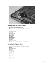
... Board 1. Follow the procedures in After Working Inside Your Computer. Remove: a) SD memory card b) battery c) bottom door d) keyboard trim e) keyboard f) optical drive g) hard drive h) WLAN card i) processor door j) thermal module 39 Follow the procedures in Before Working Inside ...Your Computer. 2. Install: a) display assembly b) palmrest c) processor door d) hard drive e) optical drive f) keyboard g) keyboard trim h) bottom door i) battery j) SD memory card 4. Tighten the screws to secure the left support frame on the computer. 2. Installing ...
... Board 1. Follow the procedures in After Working Inside Your Computer. Remove: a) SD memory card b) battery c) bottom door d) keyboard trim e) keyboard f) optical drive g) hard drive h) WLAN card i) processor door j) thermal module 39 Follow the procedures in Before Working Inside ...Your Computer. 2. Install: a) display assembly b) palmrest c) processor door d) hard drive e) optical drive f) keyboard g) keyboard trim h) bottom door i) battery j) SD memory card 4. Tighten the screws to secure the left support frame on the computer. 2. Installing ...


