Setup and Features Information Tech Sheet
Page 3
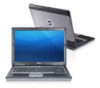
Do not store your Dell computer in the air vents. Fan noise is running. Latitude E5530 - Front View 1. display release latch 4. microphone 8. optical-drive eject button 11. audio connector 14. The computer turns on the fan when the computer gets hot. Front And Back View Figure 3. display 7. display latch 2. microphone (optional) 3. power button 9. VGA ... or allow dust to accumulate in a low-airflow environment, such as a closed briefcase, while it is normal and does not indicate a problem with the fan or the computer. camera status light (optional) 6.
Do not store your Dell computer in the air vents. Fan noise is running. Latitude E5530 - Front View 1. display release latch 4. microphone 8. optical-drive eject button 11. audio connector 14. The computer turns on the fan when the computer gets hot. Front And Back View Figure 3. display 7. display latch 2. microphone (optional) 3. power button 9. VGA ... or allow dust to accumulate in a low-airflow environment, such as a closed briefcase, while it is normal and does not indicate a problem with the fan or the computer. camera status light (optional) 6.
Setup and Features Information Tech Sheet
Page 4
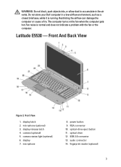
...3.0 connector 9. Secure Digital (SD) card slot 11. Do not store your Dell computer in the air vents. trackstick buttons (optional) 20. keyboard 22. cooling vents 7. The computer turns on the fan when the computer gets hot. touchpad 19. Back View 1. USB 2.0 connector 3.... wireless switch 16. HDMI connector 8. USB 3.0 connector 10. Restricting the airflow can damage the computer or cause a fire. Fan noise is running. volume control buttons Figure 4. ExpressCard slot (optional) WARNING: Do not block, push objects into, or allow dust to ...
...3.0 connector 9. Secure Digital (SD) card slot 11. Do not store your Dell computer in the air vents. trackstick buttons (optional) 20. keyboard 22. cooling vents 7. The computer turns on the fan when the computer gets hot. touchpad 19. Back View 1. USB 2.0 connector 3.... wireless switch 16. HDMI connector 8. USB 3.0 connector 10. Restricting the airflow can damage the computer or cause a fire. Fan noise is running. volume control buttons Figure 4. ExpressCard slot (optional) WARNING: Do not block, push objects into, or allow dust to ...
User Manual
Page 3
... Input/Output (I/O) Board...44 Installing the Input/Output (I/O) Board...44 Removing the Power Connector...45 Installing the Power Connector...46 Removing the System Fan...46 Installing the System Fan...48 Removing the Network Connector...48 Installing the Network Connector Jack...49 Removing the Speakers...49 Installing the Speakers...50 3 Docking Port Information...
... Input/Output (I/O) Board...44 Installing the Input/Output (I/O) Board...44 Removing the Power Connector...45 Installing the Power Connector...46 Removing the System Fan...46 Installing the System Fan...48 Removing the Network Connector...48 Installing the Network Connector Jack...49 Removing the Speakers...49 Installing the Speakers...50 3 Docking Port Information...
User Manual
Page 40
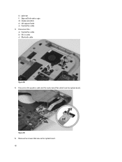
Figure 39. 5. Disconnect the speaker cable and the audio board flex cable from the system board. Remove the screws that secure the system board. 40 k) palmrest l) ExpressCard reader cage m) display assembly n) left support frame o) thermal fan cable 3. Disconnect the : a) thermal fan cable b) DC-in cable c) Bluetooth cable Figure 38. 4.
Figure 39. 5. Disconnect the speaker cable and the audio board flex cable from the system board. Remove the screws that secure the system board. 40 k) palmrest l) ExpressCard reader cage m) display assembly n) left support frame o) thermal fan cable 3. Disconnect the : a) thermal fan cable b) DC-in cable c) Bluetooth cable Figure 38. 4.
User Manual
Page 42
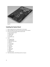
... to secure the system board to the computer. 3. Align the system board into its original position on the computer. 2. Follow the procedures in cable e) thermal fan cable 4. Installing the System Board 1. Install : a) left support frame b) display assembly c) ExpressCard reader cage d) palm rest e) thermal module f) processor door g) hard drive h) optical drive i) keyboard...
... to secure the system board to the computer. 3. Align the system board into its original position on the computer. 2. Follow the procedures in cable e) thermal fan cable 4. Installing the System Board 1. Install : a) left support frame b) display assembly c) ExpressCard reader cage d) palm rest e) thermal module f) processor door g) hard drive h) optical drive i) keyboard...
User Manual
Page 46
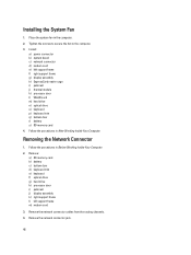
Removing the System Fan 1. Install: a) system board b) left support bracket c) display assembly d) ExpressCard reader cage e) palmrest f) thermal module g) processor door h) WLAN card i) hard drive j) optical drive k) keyboard l) keyboard trim m) ...
Removing the System Fan 1. Install: a) system board b) left support bracket c) display assembly d) ExpressCard reader cage e) palmrest f) thermal module g) processor door h) WLAN card i) hard drive j) optical drive k) keyboard l) keyboard trim m) ...

User Manual
Page 47
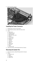
Remove the system fan cable from the computer. 47 Remove the screw that secures the system fan and lift it to remove from the routing channel. 4. e) keyboard f) optical drive g) hard drive h) WLAN card i) processor door j) thermal module k) palmrest l) ExpressCard reader cage m) display assembly n) right support frame o) left support frame p) modem card q) network connector r) system board s) power connector 3.
Remove the system fan cable from the computer. 47 Remove the screw that secures the system fan and lift it to remove from the routing channel. 4. e) keyboard f) optical drive g) hard drive h) WLAN card i) processor door j) thermal module k) palmrest l) ExpressCard reader cage m) display assembly n) right support frame o) left support frame p) modem card q) network connector r) system board s) power connector 3.
User Manual
Page 48
... connector d) modem card e) left support frame m) modem card 3. Follow the procedures in the computer. 2. Tighten the screws to secure the fan to the computer. 3. Installing the System Fan 1. Place the system fan in Before Working Inside Your Computer. 2. Remove the network connector cables from the routing channels. 4. Follow the procedures in After Working...
... connector d) modem card e) left support frame m) modem card 3. Follow the procedures in the computer. 2. Tighten the screws to secure the fan to the computer. 3. Installing the System Fan 1. Place the system fan in Before Working Inside Your Computer. 2. Remove the network connector cables from the routing channels. 4. Follow the procedures in After Working...


