Setup and Features Information Tech Sheet
Page 1
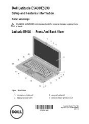
microphone (optional) 2. Latitude E5430 - display release latch 3. camera (optional) 4. Front View 1. Front And Back View Figure 1. camera status light (optional) Regulatory Model: P27G, P28G Regulatory Type: P27G001, P28G001 2011 - 09 Dell Latitude E5430/E5530 Setup and Features Information About Warnings WARNING: A WARNING indicates a potential for property damage, personal injury, or death.
microphone (optional) 2. Latitude E5430 - display release latch 3. camera (optional) 4. Front View 1. Front And Back View Figure 1. camera status light (optional) Regulatory Model: P27G, P28G Regulatory Type: P27G001, P28G001 2011 - 09 Dell Latitude E5430/E5530 Setup and Features Information About Warnings WARNING: A WARNING indicates a potential for property damage, personal injury, or death.
Setup and Features Information Tech Sheet
Page 2
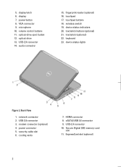
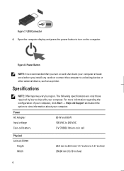
... Figure 2. 5. power connector 5. USB 3.0 connector 10. microphone 10. optical-drive eject button 12. audio connector 15. wireless switch 19. security cable slot 6. ExpressCard slot (optional) 2 display latch 6. display 7. power button 8. USB 2.0 connector 14. fingerprint reader (optional) 16. touchpad 17. device status indicators 20. USB 2.0 connector 3. modem connector (optional) 4. Secure Digital (SD) memory...
... Figure 2. 5. power connector 5. USB 3.0 connector 10. microphone 10. optical-drive eject button 12. audio connector 15. wireless switch 19. security cable slot 6. ExpressCard slot (optional) 2 display latch 6. display 7. power button 8. USB 2.0 connector 14. fingerprint reader (optional) 16. touchpad 17. device status indicators 20. USB 2.0 connector 3. modem connector (optional) 4. Secure Digital (SD) memory...
Setup and Features Information Tech Sheet
Page 3
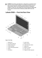
... 2. VGA connector 10. optical-drive eject button 11. audio connector 14. Do not store your Dell computer in the air vents. Front View 1. display release latch 4. microphone 8. fingerprint reader (optional) 3 display 7. optical drive 12. Latitude E5530 - Front And Back View Figure 3. WARNING: Do not block, push objects into, or allow dust to accumulate in a low...
... 2. VGA connector 10. optical-drive eject button 11. audio connector 14. Do not store your Dell computer in the air vents. Front View 1. display release latch 4. microphone 8. fingerprint reader (optional) 3 display 7. optical drive 12. Latitude E5530 - Front And Back View Figure 3. WARNING: Do not block, push objects into, or allow dust to accumulate in a low...
Setup and Features Information Tech Sheet
Page 6
... printer. Power AC Adapter Input voltage Coin-cell battery 65 W and 90 W 100 VAC to 240 VAC 3 V CR2032 lithium coin cell Physical Latitude E5430 Height Width 29.9 mm to 32.5 mm (1.17 inches to turn on the computer. Specifications NOTE: Offerings may vary by law to view ...regarding the configuration of your computer, click Start → Help and Support and select the option to ship with your computer. Open the computer display and press the power button to 1.27 inches) 350.00 mm (13.70 inches) 6 Figure 8. The following specifications are only those required...
... printer. Power AC Adapter Input voltage Coin-cell battery 65 W and 90 W 100 VAC to 240 VAC 3 V CR2032 lithium coin cell Physical Latitude E5430 Height Width 29.9 mm to 32.5 mm (1.17 inches to turn on the computer. Specifications NOTE: Offerings may vary by law to view ...regarding the configuration of your computer, click Start → Help and Support and select the option to ship with your computer. Open the computer display and press the power button to 1.27 inches) 350.00 mm (13.70 inches) 6 Figure 8. The following specifications are only those required...
User Manual
Page 2
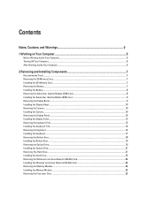
... the Subscriber Identity Module (SIM) Card 8 Installing the Subscriber Identity Module (SIM) Card 9 Removing the Display Bezel...9 Installing the Display Bezel...10 Removing the Camera...10 Installing the Camera...10 Removing the Display Panel...10 Installing the Display Panel...12 Removing the Keyboard Trim...13 Installing the Keyboard Trim...14 Removing the Keyboard...14...
... the Subscriber Identity Module (SIM) Card 8 Installing the Subscriber Identity Module (SIM) Card 9 Removing the Display Bezel...9 Installing the Display Bezel...10 Removing the Camera...10 Installing the Camera...10 Removing the Display Panel...10 Installing the Display Panel...12 Removing the Keyboard Trim...13 Installing the Keyboard Trim...14 Removing the Keyboard...14...
User Manual
Page 3
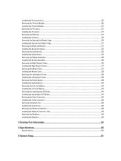
......31 Removing the Bluetooth Module...31 Installing the Bluetooth module...32 Removing the Audio Board...32 Installing the Audio Board...33 Removing the Display Assembly...33 Installing the Display Assembly...36 Removing the Right Support Frame...36 Installing the Right Support Frame...37 Removing the Modem Card...37 Installing the Modem Card...
......31 Removing the Bluetooth Module...31 Installing the Bluetooth module...32 Removing the Audio Board...32 Installing the Audio Board...33 Removing the Display Assembly...33 Installing the Display Assembly...36 Removing the Right Support Frame...36 Installing the Right Support Frame...37 Removing the Modem Card...37 Installing the Modem Card...

User Manual
Page 9
Follow the procedures in Before Working Inside Your Computer. 2. Pry up the bottom edge of the display bezel. . Slide the SIM card from the computer . 9 Removing the Display Bezel 1. Work your way around the sides and top edge of the display bezel. 4. 4. Follow the procedures in After Working Inside Your Computer. Remove the display bezel from the computer. Install the battery. 3. Remove the battery. 3. Installing the Subscriber Identity Module (SIM) Card 1. Figure 3. 5. Insert the subscriber identity module (SIM) card into the slot. 2.
Follow the procedures in Before Working Inside Your Computer. 2. Pry up the bottom edge of the display bezel. . Slide the SIM card from the computer . 9 Removing the Display Bezel 1. Work your way around the sides and top edge of the display bezel. 4. 4. Follow the procedures in After Working Inside Your Computer. Remove the display bezel from the computer. Install the battery. 3. Remove the battery. 3. Installing the Subscriber Identity Module (SIM) Card 1. Figure 3. 5. Insert the subscriber identity module (SIM) card into the slot. 2.

User Manual
Page 10
.... 10 Follow the procedures in Before Working Inside Your Computer. 2. Installing the Display Bezel 1. Follow the procedures in Before Working Inside Your Computer. 2. Remove: a) battery b) display bezel 3. Lift and remove the camera and microphone module. Place the camera and microphone ... Computer. Connect the camera cable. 4. Install: a) display bezel b) battery 5. Remove: a) battery b) display bezel 3. Follow the procedures in position on the display bezel and work around the entire bezel until it snaps onto the display assembly. 3. Removing the Camera 1. Remove the screws ...
.... 10 Follow the procedures in Before Working Inside Your Computer. 2. Installing the Display Bezel 1. Follow the procedures in Before Working Inside Your Computer. 2. Remove: a) battery b) display bezel 3. Lift and remove the camera and microphone module. Place the camera and microphone ... Computer. Connect the camera cable. 4. Install: a) display bezel b) battery 5. Remove: a) battery b) display bezel 3. Follow the procedures in position on the display bezel and work around the entire bezel until it snaps onto the display assembly. 3. Removing the Camera 1. Remove the screws ...

User Manual
Page 11
Figure 4. 4. Lift the Mylar tape and disconnect the LVDS cable from the back of the display panel. 11 Flip the display panel over. Figure 5. 5.
Figure 4. 4. Lift the Mylar tape and disconnect the LVDS cable from the back of the display panel. 11 Flip the display panel over. Figure 5. 5.

User Manual
Page 12
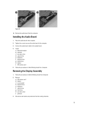
Figure 7. Installing the Display Panel 1. Attach the display panel to the display panel and attach the tape. 5. Install the screws that secure the display panel. 6. Align the display panel in its original position in the computer. 4. Install the display bezel. 7. Connect the low-voltage differential signaling (LVDS) cable to the display assembly. 3. Remove the display panel from the display assembly. Install the battery. 12 Figure 6. 6. Flip the display panel over and install the screws that secure the display brackets to the display panel. 2.
Figure 7. Installing the Display Panel 1. Attach the display panel to the display panel and attach the tape. 5. Install the screws that secure the display panel. 6. Align the display panel in its original position in the computer. 4. Install the display bezel. 7. Connect the low-voltage differential signaling (LVDS) cable to the display assembly. 3. Remove the display panel from the display assembly. Install the battery. 12 Figure 6. 6. Flip the display panel over and install the screws that secure the display brackets to the display panel. 2.
User Manual
Page 33
... in the computer. 2. Tighten the screw to secure the audio board to the system board. 4. Disconnect and remove any antennas from the computer. Removing the Display Assembly 1. Remove: a) SD memory card b) battery c) access panel d) keyboard trim e) keyboard f) optical drive g) hard drive h) processor door i) palmrest 3. Place the audio board in Before Working...
... in the computer. 2. Tighten the screw to secure the audio board to the system board. 4. Disconnect and remove any antennas from the computer. Removing the Display Assembly 1. Remove: a) SD memory card b) battery c) access panel d) keyboard trim e) keyboard f) optical drive g) hard drive h) processor door i) palmrest 3. Place the audio board in Before Working...

User Manual
Page 35
Figure 37. 35 Figure 36. 7. Figure 35. 6. Lift up the connector indicated on the system board. Remove the screws that secure the display assembly in place.
Figure 37. 35 Figure 36. 7. Figure 35. 6. Lift up the connector indicated on the system board. Remove the screws that secure the display assembly in place.
User Manual
Page 36
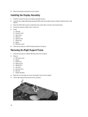
...battery c) bottom door d) keyboard trim e) optical drive f) hard drive g) processor door h) palmrest i) display assembly 3. Remove the screws that secure the display assembly in place. 2. Installing the Display Assembly 1. Insert the low-voltage differential signaling (LVDS) cable and wireless antenna cables through the holes ...cable along its compartment and connect the connector to the system board. 4. Removing the Right Support Frame 1. Remove the display assembly from the computer. 36 Follow the procedures in After Working Inside Your Computer. 8. Install the screws that secure...
...battery c) bottom door d) keyboard trim e) optical drive f) hard drive g) processor door h) palmrest i) display assembly 3. Remove the screws that secure the display assembly in place. 2. Installing the Display Assembly 1. Insert the low-voltage differential signaling (LVDS) cable and wireless antenna cables through the holes ...cable along its compartment and connect the connector to the system board. 4. Removing the Right Support Frame 1. Remove the display assembly from the computer. 36 Follow the procedures in After Working Inside Your Computer. 8. Install the screws that secure...
User Manual
Page 37
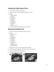
Install: a) display assembly b) palmrest c) processor door d) hard drive e) optical drive f) keyboard g) keyboard trim h) bottom doorl i) battery j) SD memory card 4. Tighten the screws to secure the right support ... the Right Support Frame 1. Removing the Modem Card 1. Remove: a) SD memory card b) battery c) bottom door d) keyboard trim e) keyboard f) optical drive g) hard drive h) processor door i) palmrest j) display assembly k) right support frame 3.
Install: a) display assembly b) palmrest c) processor door d) hard drive e) optical drive f) keyboard g) keyboard trim h) bottom doorl i) battery j) SD memory card 4. Tighten the screws to secure the right support ... the Right Support Frame 1. Removing the Modem Card 1. Remove: a) SD memory card b) battery c) bottom door d) keyboard trim e) keyboard f) optical drive g) hard drive h) processor door i) palmrest j) display assembly k) right support frame 3.
User Manual
Page 38
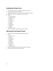
... the procedures in the computer. 2. Place the modem card on the Input/Output (I/O) board in After Working Inside Your Computer. Install: a) right support frame b) display assembly c) palmrest d) processor door e) hard drive f) optical drive g) keyboard h) keyboard trim i) bottom door j) battery k) SD memory card 6. Follow the procedures...the computer. 5. Remove: a) SD memory card b) battery c) bottom door d) keyboard trim e) keyboard f) optical drive g) hard drive h) processor door i) palmrest j) display assembly 3. Tighten the screw to secure the modem card to the computer. 4.
... the procedures in the computer. 2. Place the modem card on the Input/Output (I/O) board in After Working Inside Your Computer. Install: a) right support frame b) display assembly c) palmrest d) processor door e) hard drive f) optical drive g) keyboard h) keyboard trim i) bottom door j) battery k) SD memory card 6. Follow the procedures...the computer. 5. Remove: a) SD memory card b) battery c) bottom door d) keyboard trim e) keyboard f) optical drive g) hard drive h) processor door i) palmrest j) display assembly 3. Tighten the screw to secure the modem card to the computer. 4.
User Manual
Page 39
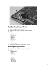
... computer. 3. Place the left support frame to secure the left support frame on the computer. 2. Follow the procedures in After Working Inside Your Computer. Install: a) display assembly b) palmrest c) processor door d) hard drive e) optical drive f) keyboard g) keyboard trim h) bottom door i) battery j) SD memory card 4.
... computer. 3. Place the left support frame to secure the left support frame on the computer. 2. Follow the procedures in After Working Inside Your Computer. Install: a) display assembly b) palmrest c) processor door d) hard drive e) optical drive f) keyboard g) keyboard trim h) bottom door i) battery j) SD memory card 4.
User Manual
Page 40
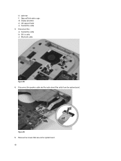
k) palmrest l) ExpressCard reader cage m) display assembly n) left support frame o) thermal fan cable 3. Disconnect the : a) thermal fan cable b) DC-in cable c) Bluetooth cable Figure 38. 4. Remove the screws that secure the system board. 40 Disconnect the speaker cable and the audio board flex cable from the system board. Figure 39. 5.
k) palmrest l) ExpressCard reader cage m) display assembly n) left support frame o) thermal fan cable 3. Disconnect the : a) thermal fan cable b) DC-in cable c) Bluetooth cable Figure 38. 4. Remove the screws that secure the system board. 40 Disconnect the speaker cable and the audio board flex cable from the system board. Figure 39. 5.
User Manual
Page 42
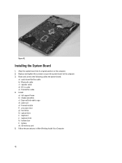
Install : a) left support frame b) display assembly c) ExpressCard reader cage d) palm rest e) thermal module f) processor door g) hard drive h) optical drive i) keyboard j) keyboard trim k) bottom door l) battery m) SD memory card 5. Figure 42. ...
Install : a) left support frame b) display assembly c) ExpressCard reader cage d) palm rest e) thermal module f) processor door g) hard drive h) optical drive i) keyboard j) keyboard trim k) bottom door l) battery m) SD memory card 5. Figure 42. ...
User Manual
Page 43
... memory card b) ExpressCard c) battery d) access panel e) keyboard trim f) optical drive g) hard drive h) WLAN card i) right base panel j) thermal module k) palmrest l) ExpressCard reader cage m) display assembly n) left support frame c) display assembly d) ExpressCard reader cage e) palmrest f) thermal module g) right base panel h) WLAN card i) hard drive j) optical drive k) keyboard l) keyboard trim m) access panel n) battery o) ExpressCard...
... memory card b) ExpressCard c) battery d) access panel e) keyboard trim f) optical drive g) hard drive h) WLAN card i) right base panel j) thermal module k) palmrest l) ExpressCard reader cage m) display assembly n) left support frame c) display assembly d) ExpressCard reader cage e) palmrest f) thermal module g) right base panel h) WLAN card i) hard drive j) optical drive k) keyboard l) keyboard trim m) access panel n) battery o) ExpressCard...
User Manual
Page 44
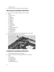
... b) battery c) bottom door d) keyboard trim e) keyboard f) optical drive g) hard drive h) WLAN card i) processor door j) thermal module k) palmrest l) ExpressCard reader cage m) display assembly n) right support frame o) left support frame c) right support frame d) display assembly e) ExpressCard reader cage 44 Remove the screws that secure the Input/Output (I /O) board to the computer. 3. Lift the Input...
... b) battery c) bottom door d) keyboard trim e) keyboard f) optical drive g) hard drive h) WLAN card i) processor door j) thermal module k) palmrest l) ExpressCard reader cage m) display assembly n) right support frame o) left support frame c) right support frame d) display assembly e) ExpressCard reader cage 44 Remove the screws that secure the Input/Output (I /O) board to the computer. 3. Lift the Input...


