Latitude E5410 14 - Dell
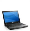
Latitude E5410 14
View Results Below
Free Dell Latitude E5410 manuals!
Problems with Dell Latitude E5410?
Ask a Question
Free Dell Latitude E5410 manuals!
Problems with Dell Latitude E5410?
Ask a Question
Related Manual Pages

Similar Questions

Hp 14-an013nr 14-inch Notebook Amd E2-7110 Qc, 4gb Ram,
Does this Notebook have 32 or 64 bit operating system?
Does this Notebook have 32 or 64 bit operating system?
(Posted by chris321 7 years ago)

Does My Dell Inspiron M5040 Support Fifa 14?
Hi, I am looking to purchase Fifa 14 for my Inspiron M5040 and I have no idea if it would support it...
Hi, I am looking to purchase Fifa 14 for my Inspiron M5040 and I have no idea if it would support it...
(Posted by lauriehowell96 10 years ago)

Dell Inspiron Stops While Playing Fifa 14
Why mt dell inspirion laptop is stopping while playing Fifa 14. I can play 30 minutes and then it sh...
Why mt dell inspirion laptop is stopping while playing Fifa 14. I can play 30 minutes and then it sh...
(Posted by medhrk 10 years ago)