

Service Manual
Page 15
... Customer kit, memory CUS, 32MB, DIMM, SDRAM 8 module, 32-MB Customer kit, memory module, 64-MB CUS, 64MB, DIMM, SDRAM Customer kit, memory module, 128-MB CUS, 128MB, DIMM, SDRAM Customer kit, memory module, 192-MB CUS, 192MB, DIMM, SDRAM Customer kit, memory module, 256-MB CUS, 256MB, DIMM, SDRAM 8 Dell Latitude CPt V/CPt S Series and CPx H/CPx J Series Service Manual
... Customer kit, memory CUS, 32MB, DIMM, SDRAM 8 module, 32-MB Customer kit, memory module, 64-MB CUS, 64MB, DIMM, SDRAM Customer kit, memory module, 128-MB CUS, 128MB, DIMM, SDRAM Customer kit, memory module, 192-MB CUS, 192MB, DIMM, SDRAM Customer kit, memory module, 256-MB CUS, 256MB, DIMM, SDRAM 8 Dell Latitude CPt V/CPt S Series and CPx H/CPx J Series Service Manual

Service Manual
Page 16
Memory door assembly DOOR, MEM, MET, NB System board assembly, SVCKIT, MB ASSY, PWA, ENGINE 22 service kit Service tag installation diskette DSK, BIOS, FLDSVC, F3, ... Kit, latch, slider, Button Foot, Rubber, Black (4 each) Foot, Rubber, Strike Zone, Black LTCH, BTN, Module Foot, Rbr, Blk Foot, Rbr, Strike Zone, Blk support.dell.com Dell Latitude CPt V/CPt S Series and CPx H/CPx J Series Service Manual 9
Memory door assembly DOOR, MEM, MET, NB System board assembly, SVCKIT, MB ASSY, PWA, ENGINE 22 service kit Service tag installation diskette DSK, BIOS, FLDSVC, F3, ... Kit, latch, slider, Button Foot, Rubber, Black (4 each) Foot, Rubber, Strike Zone, Black LTCH, BTN, Module Foot, Rbr, Blk Foot, Rbr, Strike Zone, Blk support.dell.com Dell Latitude CPt V/CPt S Series and CPx H/CPx J Series Service Manual 9

Service Manual
Page 19
... work surface. 3. Release the memory module cover. Keep holding the latch open while pulling the device out of the modular bay with the other hand (see Figure 7). 1. Insert a flat-blade screwdriver under the indentation in the bottom case assembly and lift the cover. 12 Dell Latitude CPt V/CPt S Series and CPx H/CPx J Series Service Manual Remove the...
... work surface. 3. Release the memory module cover. Keep holding the latch open while pulling the device out of the modular bay with the other hand (see Figure 7). 1. Insert a flat-blade screwdriver under the indentation in the bottom case assembly and lift the cover. 12 Dell Latitude CPt V/CPt S Series and CPx H/CPx J Series Service Manual Remove the...

Service Manual
Page 20
.... 1. The slots on the system board are not interchangeable. If you . support.dell.com Dell Latitude CPt V/CPt S Series and CPx H/CPx J Series Service Manual 13 inner tabs (2 per socket) memory module sockets (2) DIMM A DIMM B 1. A 192-MB memory module inserted with the double-stacked memory chips facing you only have one memory module, install it in only one way. To release...
.... 1. The slots on the system board are not interchangeable. If you . support.dell.com Dell Latitude CPt V/CPt S Series and CPx H/CPx J Series Service Manual 13 inner tabs (2 per socket) memory module sockets (2) DIMM A DIMM B 1. A 192-MB memory module inserted with the double-stacked memory chips facing you only have one memory module, install it in only one way. To release...

Service Manual
Page 21
... down on a flat work surface. 10-mm screws (7) M2.5x10 14 Dell Latitude CPt V/CPt S Series and CPx H/CPx J Series Service Manual Close the display assembly, and turn the computer upside down until it . 4. With the module at a 45-degree angle, press the memory module's edge connector firmly into place. Remove the main battery and secondary battery...
... down on a flat work surface. 10-mm screws (7) M2.5x10 14 Dell Latitude CPt V/CPt S Series and CPx H/CPx J Series Service Manual Close the display assembly, and turn the computer upside down until it . 4. With the module at a 45-degree angle, press the memory module's edge connector firmly into place. Remove the main battery and secondary battery...
Service Manual
Page 42
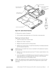
... the PC Card slot. 6. Replace the microprocessor, the palmrest assembly, the display assembly and the keyboard assembly. support.dell.com Dell Latitude CPt V/CPt S Series and CPx H/CPx J Series Service Manual 35 NOTE: Be sure to transfer the memory module(s) to enter the system's service tag number into the appropriate drive, and turn on the system board bottom...
... the PC Card slot. 6. Replace the microprocessor, the palmrest assembly, the display assembly and the keyboard assembly. support.dell.com Dell Latitude CPt V/CPt S Series and CPx H/CPx J Series Service Manual 35 NOTE: Be sure to transfer the memory module(s) to enter the system's service tag number into the appropriate drive, and turn on the system board bottom...
Service Manual
Page 47
..., 18 modular bay devices removal, 12 module latch assemblies removal, 37 screw identification and tightening, 3 sockets memory module, 13 SuperDisk LS-120 drive removal, 12 system board assembly removal, 18 thermal cooling assembly removal, 36 tools, 2 travel module removal, 12 ZIF connectors, 5 palmrest assembly removal, 30 2 Dell Latitude CPt V/CPt S Series and CPx H/Cpx J Series Service Manual
..., 18 modular bay devices removal, 12 module latch assemblies removal, 37 screw identification and tightening, 3 sockets memory module, 13 SuperDisk LS-120 drive removal, 12 system board assembly removal, 18 thermal cooling assembly removal, 36 tools, 2 travel module removal, 12 ZIF connectors, 5 palmrest assembly removal, 30 2 Dell Latitude CPt V/CPt S Series and CPx H/Cpx J Series Service Manual


