
Service Manual
Page 4
... Parts and Assemblies 6 Removing and Replacing Field-Replaceable Parts and Assemblies 10 Hard-Disk Drive Assembly 11 Removing the Hard-Disk Drive Assembly 11 Replacing the Hard-Disk Drive Assembly 11 Modular Bay Devices (Diskette Drive, CD-ROM Drive, DVD-ROM Drive, CD-RW Drive, SuperDisk LS-120 Drive, Battery, or Travel Module) . . . . 12 Memory Module Cover 12 Removing the Memory...
... Parts and Assemblies 6 Removing and Replacing Field-Replaceable Parts and Assemblies 10 Hard-Disk Drive Assembly 11 Removing the Hard-Disk Drive Assembly 11 Replacing the Hard-Disk Drive Assembly 11 Modular Bay Devices (Diskette Drive, CD-ROM Drive, DVD-ROM Drive, CD-RW Drive, SuperDisk LS-120 Drive, Battery, or Travel Module) . . . . 12 Memory Module Cover 12 Removing the Memory...
Service Manual
Page 5
Figure 2. Figure 4. Figure 8. Figure 9. Figure 10. Figure 12. Computer Orientation 1 Main Battery Removal 3 Screw Identification 3 Disconnecting a Cable from an Interface Connector 5 Exploded View-Computer 10 Hard-Disk Drive Assembly Removal 11 Modular Bay Device Removal 12 Memory Module Removal 13 Removing the Keyboard Assembly Screws 14 Keyboard Assembly Removal 15 Keyboard and Track...
Figure 2. Figure 4. Figure 8. Figure 9. Figure 10. Figure 12. Computer Orientation 1 Main Battery Removal 3 Screw Identification 3 Disconnecting a Cable from an Interface Connector 5 Exploded View-Computer 10 Hard-Disk Drive Assembly Removal 11 Modular Bay Device Removal 12 Memory Module Removal 13 Removing the Keyboard Assembly Screws 14 Keyboard Assembly Removal 15 Keyboard and Track...

Service Manual
Page 11
Hard-Disk Drive Assembly: M3.0 x 5 (1 each) Keyboard Assembly: M2.5 x 10 (7 each) Display Assembly: M2.5 x 4 (3 each) Display Assembly Bezel: Rubber Screw Covers (4 each) Plastic Screw Covers (2 each) Display Assembly .... When you are removing and replacing components, photocopy the Table 1 placement mat as a tool to your system) Thermal Cooling Assembly and Exhaust Fan: M2.5 x 4 (2 each) 4 Dell Latitude CPt V/CPt S Series and CPx H/CPx J Series Service Manual
Hard-Disk Drive Assembly: M3.0 x 5 (1 each) Keyboard Assembly: M2.5 x 10 (7 each) Display Assembly: M2.5 x 4 (3 each) Display Assembly Bezel: Rubber Screw Covers (4 each) Plastic Screw Covers (2 each) Display Assembly .... When you are removing and replacing components, photocopy the Table 1 placement mat as a tool to your system) Thermal Cooling Assembly and Exhaust Fan: M2.5 x 4 (2 each) 4 Dell Latitude CPt V/CPt S Series and CPx H/CPx J Series Service Manual

Service Manual
Page 13
..., zzz* Hard-disk drive interface board PWA, INTERCON, HD * Substitute the drive capacity for xxxxGB, the drive height for yyMM, and zzz for reference only. Customer kit, AC adapter AC adapter Power cable, U.S. Some parts may only be available as part of a service kit or assembly and are provided for the manufacturer's name. 6 Dell Latitude CPt...
..., zzz* Hard-disk drive interface board PWA, INTERCON, HD * Substitute the drive capacity for xxxxGB, the drive height for yyMM, and zzz for reference only. Customer kit, AC adapter AC adapter Power cable, U.S. Some parts may only be available as part of a service kit or assembly and are provided for the manufacturer's name. 6 Dell Latitude CPt...

Service Manual
Page 14
Hard-disk drive carrier ASSY, CARR, HD Palmrest assembly ASSY, PLMRST, TPAD 20 Palmrest screws (5) SCR, M2.5X20, PHH, LP, ZPS 19 Reserve battery CUS, BTRY, RESERVE Euro-... 14.1-inch flex cable ASSY, CBL, FLX, TFT 12.1-inch flex cable ASSY, CBL, FLX, W/EXTN,12.1 14 14 16 16 14 16, 17 support.dell.com Dell Latitude CPt V/CPt S Series and CPx H/CPx J Series Service Manual 7
Hard-disk drive carrier ASSY, CARR, HD Palmrest assembly ASSY, PLMRST, TPAD 20 Palmrest screws (5) SCR, M2.5X20, PHH, LP, ZPS 19 Reserve battery CUS, BTRY, RESERVE Euro-... 14.1-inch flex cable ASSY, CBL, FLX, TFT 12.1-inch flex cable ASSY, CBL, FLX, W/EXTN,12.1 14 14 16 16 14 16, 17 support.dell.com Dell Latitude CPt V/CPt S Series and CPx H/CPx J Series Service Manual 7

Service Manual
Page 17
display assembly keyboard palmrest assembly hard-disk drive internal modem (may not apply to your system) system board main battery case plug for modem bottom case assembly modular bay device The following subsections provide instructions for removing and replacing field-replaceable parts and assemblies. 10 Dell Latitude CPt V/CPt S Series and CPx H/CPx J Series Service Manual
display assembly keyboard palmrest assembly hard-disk drive internal modem (may not apply to your system) system board main battery case plug for modem bottom case assembly modular bay device The following subsections provide instructions for removing and replacing field-replaceable parts and assemblies. 10 Dell Latitude CPt V/CPt S Series and CPx H/CPx J Series Service Manual

Service Manual
Page 18
... left side of the computer. 2. Push the drive assembly into the opening on the left side of computer 5-mm screw M3.0x5 hard-disk drive door 1. bottom of the computer. 3. Slide the drive door down until it aligns with the cover. 3. support.dell.com Dell Latitude CPt V/CPt S Series and CPx H/CPx J Series Service Manual 11 Remove the main...
... left side of the computer. 2. Push the drive assembly into the opening on the left side of computer 5-mm screw M3.0x5 hard-disk drive door 1. bottom of the computer. 3. Slide the drive door down until it aligns with the cover. 3. support.dell.com Dell Latitude CPt V/CPt S Series and CPx H/CPx J Series Service Manual 11 Remove the main...
Service Manual
Page 41
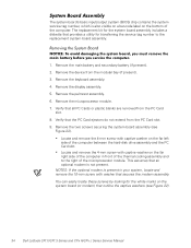
... assembly. You can easily locate these screws by looking for transferring the service tag number to the right of the computer between the hard-disk drive assembly and the PC Card slot. Remove the palmrest assembly. 6. The system board's basic input/output system (BIOS) chip contains ...of the computer in front of the computer. Remove the two screws securing the system board assembly (see Figure 22). 34 Dell Latitude CPt V/CPt S Series and CPx H/CPx J Series Service Manual This assumes that provides a utility for the white marks on the bottom of the thermal cooling assembly ...
... assembly. You can easily locate these screws by looking for transferring the service tag number to the right of the computer between the hard-disk drive assembly and the PC Card slot. Remove the palmrest assembly. 6. The system board's basic input/output system (BIOS) chip contains ...of the computer in front of the computer. Remove the two screws securing the system board assembly (see Figure 22). 34 Dell Latitude CPt V/CPt S Series and CPx H/CPx J Series Service Manual This assumes that provides a utility for the white marks on the bottom of the thermal cooling assembly ...
Service Manual
Page 47
hard-disk drive assembly removal, 11 reserve battery removal, 32 inverter, 12.1-inch LCD panel removal, 26 replacement, 27 keyboard assembly removal, 15 memory module removal, 13 memory ... bay devices removal, 12 module latch assemblies removal, 37 screw identification and tightening, 3 sockets memory module, 13 SuperDisk LS-120 drive removal, 12 system board assembly removal, 18 thermal cooling assembly removal, 36 tools, 2 travel module removal, 12 ZIF connectors, 5 palmrest assembly removal, 30 2 Dell Latitude CPt V/CPt S Series and CPx H/Cpx J Series Service Manual
hard-disk drive assembly removal, 11 reserve battery removal, 32 inverter, 12.1-inch LCD panel removal, 26 replacement, 27 keyboard assembly removal, 15 memory module removal, 13 memory ... bay devices removal, 12 module latch assemblies removal, 37 screw identification and tightening, 3 sockets memory module, 13 SuperDisk LS-120 drive removal, 12 system board assembly removal, 18 thermal cooling assembly removal, 36 tools, 2 travel module removal, 12 ZIF connectors, 5 palmrest assembly removal, 30 2 Dell Latitude CPt V/CPt S Series and CPx H/Cpx J Series Service Manual
System Information Guide (multilanguage: English, Japanese, Chinese-Traditional, Chinese-Simplified, Korean, Thai)
Page 5
... and install these updates before consulting any options you need to your hard-disk drive. Always read these options in your computer. support.dell.com DELL CONFIDENTIAL - (Rev. 11/3/98) FILE LOCATION: \\Pd-xuzhan\d\FrameMaker\Dell\sndmm003\en\999CCA00en.fm ™ ™ Your Dell Latitude portable computer accessories box includes a reduced set of computer features, instructions on...
... and install these updates before consulting any options you need to your hard-disk drive. Always read these options in your computer. support.dell.com DELL CONFIDENTIAL - (Rev. 11/3/98) FILE LOCATION: \\Pd-xuzhan\d\FrameMaker\Dell\sndmm003\en\999CCA00en.fm ™ ™ Your Dell Latitude portable computer accessories box includes a reduced set of computer features, instructions on...
System Information Guide (multilanguage: English, Japanese, Chinese-Traditional, Chinese-Simplified, Korean, Thai)
Page 10
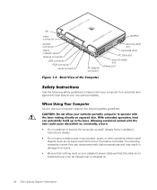
... power cable and that the cable is not located where it can be tripped over or stepped on. Preliminary 1/25/00 1-6 Dell Latitude System Information As you use your computer, observe the following safety guidelines to help ensure your own personal safety. (Rev. 11/3/98...) FILE LOCATION: \\Pd-xuzhan\d\FrameMaker\Dell\sndmm003\en\999CCA00en.fm fan video connector parallel connector status indicator panel docking connector USB connector PS/2 connector serial connector speaker security cable slot hard-disk drive PC Card slot AC adapter connector security cable slot infrared...
... power cable and that the cable is not located where it can be tripped over or stepped on. Preliminary 1/25/00 1-6 Dell Latitude System Information As you use your computer, observe the following safety guidelines to help ensure your own personal safety. (Rev. 11/3/98...) FILE LOCATION: \\Pd-xuzhan\d\FrameMaker\Dell\sndmm003\en\999CCA00en.fm fan video connector parallel connector status indicator panel docking connector USB connector PS/2 connector serial connector speaker security cable slot hard-disk drive PC Card slot AC adapter connector security cable slot infrared...

System Information Guide (multilanguage: English, Japanese, Chinese-Traditional, Chinese-Simplified, Korean, Thai)
Page 12
...to avoid bending any connector pins. Preliminary 1/25/00 1-8 Dell Latitude System Information You can put your computer through an X-ray security machine, but never put your computer between environments with the hard-disk drive removed from the top of commercial window cleaner. As you disconnect...Clean the display with care. If the display contains grease or some other mechanical shocks. • Protect your computer, battery, and hard-disk drive from its pins. • When removing a memory module from the system board or disconnecting a peripheral device from the computer, wait...
...to avoid bending any connector pins. Preliminary 1/25/00 1-8 Dell Latitude System Information You can put your computer through an X-ray security machine, but never put your computer between environments with the hard-disk drive removed from the top of commercial window cleaner. As you disconnect...Clean the display with care. If the display contains grease or some other mechanical shocks. • Protect your computer, battery, and hard-disk drive from its pins. • When removing a memory module from the system board or disconnecting a peripheral device from the computer, wait...


