
Service Manual
Page 4
...-ROM Drive, DVD-ROM Drive, CD-RW Drive, SuperDisk LS-120 Drive, Battery, or Travel Module) . . . . 12 Memory Module Cover 12 Removing the Memory Module Cover 12 Memory Modules 13 Removing the Memory Modules 13 Replacing the Memory Modules 13 Keyboard Assembly 14 Removing the Keyboard Assembly 14 Replacing the Keyboard Assembly 16 Microprocessor Module...
...-ROM Drive, DVD-ROM Drive, CD-RW Drive, SuperDisk LS-120 Drive, Battery, or Travel Module) . . . . 12 Memory Module Cover 12 Removing the Memory Module Cover 12 Memory Modules 13 Removing the Memory Modules 13 Replacing the Memory Modules 13 Keyboard Assembly 14 Removing the Keyboard Assembly 14 Replacing the Keyboard Assembly 16 Microprocessor Module...
Service Manual
Page 5
... Battery Removal 3 Screw Identification 3 Disconnecting a Cable from an Interface Connector 5 Exploded View-Computer 10 Hard-Disk Drive Assembly Removal 11 Modular Bay Device Removal 12 Memory Module Removal 13 Removing the Keyboard Assembly Screws 14 Keyboard Assembly Removal 15 Keyboard and Track Stick Cables and Connectors 16 Microprocessor Module Removal 18...
... Battery Removal 3 Screw Identification 3 Disconnecting a Cable from an Interface Connector 5 Exploded View-Computer 10 Hard-Disk Drive Assembly Removal 11 Modular Bay Device Removal 12 Memory Module Removal 13 Removing the Keyboard Assembly Screws 14 Keyboard Assembly Removal 15 Keyboard and Track Stick Cables and Connectors 16 Microprocessor Module Removal 18...

Service Manual
Page 15
... Customer kit, memory CUS, 32MB, DIMM, SDRAM 8 module, 32-MB Customer kit, memory module, 64-MB CUS, 64MB, DIMM, SDRAM Customer kit, memory module, 128-MB CUS, 128MB, DIMM, SDRAM Customer kit, memory module, 192-MB CUS, 192MB, DIMM, SDRAM Customer kit, memory module, 256-MB CUS, 256MB, DIMM, SDRAM 8 Dell Latitude CPt V/CPt S Series and CPx H/CPx J Series...
... Customer kit, memory CUS, 32MB, DIMM, SDRAM 8 module, 32-MB Customer kit, memory module, 64-MB CUS, 64MB, DIMM, SDRAM Customer kit, memory module, 128-MB CUS, 128MB, DIMM, SDRAM Customer kit, memory module, 192-MB CUS, 192MB, DIMM, SDRAM Customer kit, memory module, 256-MB CUS, 256MB, DIMM, SDRAM 8 Dell Latitude CPt V/CPt S Series and CPx H/CPx J Series...

Service Manual
Page 16
Memory door assembly DOOR, MEM, MET, NB System board assembly, SVCKIT, MB ASSY, PWA, ENGINE 22 service kit Service tag installation diskette DSK, BIOS, FLDSVC, F3, ... Kit, latch, slider, Button Foot, Rubber, Black (4 each) Foot, Rubber, Strike Zone, Black LTCH, BTN, Module Foot, Rbr, Blk Foot, Rbr, Strike Zone, Blk support.dell.com Dell Latitude CPt V/CPt S Series and CPx H/CPx J Series Service Manual 9
Memory door assembly DOOR, MEM, MET, NB System board assembly, SVCKIT, MB ASSY, PWA, ENGINE 22 service kit Service tag installation diskette DSK, BIOS, FLDSVC, F3, ... Kit, latch, slider, Button Foot, Rubber, Black (4 each) Foot, Rubber, Strike Zone, Black LTCH, BTN, Module Foot, Rbr, Blk Foot, Rbr, Strike Zone, Blk support.dell.com Dell Latitude CPt V/CPt S Series and CPx H/CPx J Series Service Manual 9

Service Manual
Page 19
Close the display, and turn the computer upside down on a flat work surface. 2. Remove the main battery and secondary battery (if present). 2. Release the memory module cover. Keep holding the latch open while pulling the device out of the modular bay with the other hand (see Figure 7). 1. latch lock 1. ...the computer upside down on a flat work surface. 3. Insert a flat-blade screwdriver under the indentation in the bottom case assembly and lift the cover. 12 Dell Latitude CPt V/CPt S Series and CPx H/CPx J Series Service Manual Push the module latch toward the unlock icon.
Close the display, and turn the computer upside down on a flat work surface. 2. Remove the main battery and secondary battery (if present). 2. Release the memory module cover. Keep holding the latch open while pulling the device out of the modular bay with the other hand (see Figure 7). 1. latch lock 1. ...the computer upside down on a flat work surface. 3. Insert a flat-blade screwdriver under the indentation in the bottom case assembly and lift the cover. 12 Dell Latitude CPt V/CPt S Series and CPx H/CPx J Series Service Manual Push the module latch toward the unlock icon.

Service Manual
Page 20
Remove the memory module cover. 3. support.dell.com Dell Latitude CPt V/CPt S Series and CPx H/CPx J Series Service Manual 13 To release a memory module from the socket. If you . The slots on the system board are keyed, or designed to disengage from its socket. 1. The module should pop up slightly (see Figure 8). 4. NOTES: 192-MB memory modules are not...
Remove the memory module cover. 3. support.dell.com Dell Latitude CPt V/CPt S Series and CPx H/CPx J Series Service Manual 13 To release a memory module from the socket. If you . The slots on the system board are keyed, or designed to disengage from its socket. 1. The module should pop up slightly (see Figure 8). 4. NOTES: 192-MB memory modules are not...

Service Manual
Page 21
... down on a flat work surface. 10-mm screws (7) M2.5x10 14 Dell Latitude CPt V/CPt S Series and CPx H/CPx J Series Service Manual If you do not hear a click as each end of the memory module socket. Replace the memory module cover. 1. Close the display assembly, and turn the computer upside down until it clicks into the...
... down on a flat work surface. 10-mm screws (7) M2.5x10 14 Dell Latitude CPt V/CPt S Series and CPx H/CPx J Series Service Manual If you do not hear a click as each end of the memory module socket. Replace the memory module cover. 1. Close the display assembly, and turn the computer upside down until it clicks into the...
Service Manual
Page 42
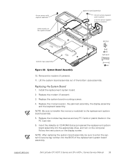
..., the palmrest assembly, the display assembly and the keyboard assembly. Follow the instructions on the computer. support.dell.com Dell Latitude CPt V/CPt S Series and CPx H/CPx J Series Service Manual 35 Insert the diskette (or CD-ROM) that accompanied the replacement system board assembly ...into the BIOS of the bottom case assembly. 1. Install the replacement system board. 2. NOTE: Be sure to transfer the memory...
..., the palmrest assembly, the display assembly and the keyboard assembly. Follow the instructions on the computer. support.dell.com Dell Latitude CPt V/CPt S Series and CPx H/CPx J Series Service Manual 35 Insert the diskette (or CD-ROM) that accompanied the replacement system board assembly ...into the BIOS of the bottom case assembly. 1. Install the replacement system board. 2. NOTE: Be sure to transfer the memory...
Service Manual
Page 47
... bay devices removal, 12 module latch assemblies removal, 37 screw identification and tightening, 3 sockets memory module, 13 SuperDisk LS-120 drive removal, 12 system board assembly removal, 18 thermal cooling assembly removal, 36 tools, 2 travel module removal, 12 ZIF connectors, 5 palmrest assembly removal, 30 2 Dell Latitude CPt V/CPt S Series and CPx H/Cpx J Series Service Manual
... bay devices removal, 12 module latch assemblies removal, 37 screw identification and tightening, 3 sockets memory module, 13 SuperDisk LS-120 drive removal, 12 system board assembly removal, 18 thermal cooling assembly removal, 36 tools, 2 travel module removal, 12 ZIF connectors, 5 palmrest assembly removal, 30 2 Dell Latitude CPt V/CPt S Series and CPx H/Cpx J Series Service Manual

System Information Guide (multilanguage: English, Japanese, Chinese-Traditional, Chinese-Simplified, Korean, Thai)
Page 12
... a cable, pull on its connector or on or within the computer. Hold a component such as cloth or paper. DELL CONFIDENTIAL - Also, before removing the memory module or disconnecting the device to help avoid possible damage to the system board. • Before you clean your computer ... checked by its edges, not its pins. • When removing a memory module from the system board or disconnecting a peripheral device from the top of commercial window cleaner. Preliminary 1/25/00 1-8 Dell Latitude System Information Apply the cleaner to avoid bending any connector pins. If the...
... a cable, pull on its connector or on or within the computer. Hold a component such as cloth or paper. DELL CONFIDENTIAL - Also, before removing the memory module or disconnecting the device to help avoid possible damage to the system board. • Before you clean your computer ... checked by its edges, not its pins. • When removing a memory module from the system board or disconnecting a peripheral device from the top of commercial window cleaner. Preliminary 1/25/00 1-8 Dell Latitude System Information Apply the cleaner to avoid bending any connector pins. If the...
System Information Guide (multilanguage: English, Japanese, Chinese-Traditional, Chinese-Simplified, Korean, Thai)
Page 14
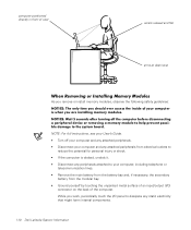
DELL CONFIDENTIAL - While you remove or install memory modules, observe the following safety guidelines: NOTE: For full instructions, see your User's Guide. • Turn off your computer and any attached peripherals. • Disconnect ... from the modular bay. • Ground yourself by touching the unpainted metal surface of the computer. Preliminary 1/25/00 1-10 Dell Latitude System Information (Rev. 11/3/98) FILE LOCATION: \\Pd-xuzhan\d\FrameMaker\Dell\sndmm003\en\999CCA00en.fm computer positioned directly in front of user wrists relaxed and flat arms at desk level As...
DELL CONFIDENTIAL - While you remove or install memory modules, observe the following safety guidelines: NOTE: For full instructions, see your User's Guide. • Turn off your computer and any attached peripherals. • Disconnect ... from the modular bay. • Ground yourself by touching the unpainted metal surface of the computer. Preliminary 1/25/00 1-10 Dell Latitude System Information (Rev. 11/3/98) FILE LOCATION: \\Pd-xuzhan\d\FrameMaker\Dell\sndmm003\en\999CCA00en.fm computer positioned directly in front of user wrists relaxed and flat arms at desk level As...
System Information Guide (multilanguage: English, Japanese, Chinese-Traditional, Chinese-Simplified, Korean, Thai)
Page 15
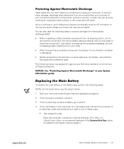
...install the component. Just before you are ready to an electrical outlet and preserve your data in a static-safe area. support.dell.com DELL CONFIDENTIAL - You can do not remove the component from your body before unwrapping the antistatic packaging, be sure to remove any...close all sensitive components in one of your computer's electronic components, such as a memory module. Preliminary 1/25/00 Dell Latitude System Information 1-11 (Rev. 11/3/98) FILE LOCATION: \\Pd-xuzhan\d\FrameMaker\Dell\sndmm003\en\999CCA00en.fm Static electricity can also take the following steps to prevent ...
...install the component. Just before you are ready to an electrical outlet and preserve your data in a static-safe area. support.dell.com DELL CONFIDENTIAL - You can do not remove the component from your body before unwrapping the antistatic packaging, be sure to remove any...close all sensitive components in one of your computer's electronic components, such as a memory module. Preliminary 1/25/00 Dell Latitude System Information 1-11 (Rev. 11/3/98) FILE LOCATION: \\Pd-xuzhan\d\FrameMaker\Dell\sndmm003\en\999CCA00en.fm Static electricity can also take the following steps to prevent ...


