

Service Manual
Page 11
Hard-Disk Drive Assembly: M3.0 x 5 (1 each) Keyboard Assembly: M2.5 x 10 (7 each) Display Assembly: M2.5 x 4 (3 each) Display Assembly Bezel: Rubber Screw Covers (4 each) Plastic Screw Covers...4 (2 each) (w/o modem assembly) M2.5 x 4 (1 each) M2.5 x 10 (1 each) (w/ modem assembly) Microprocessor Shield Assembly: 3 captive and 2 removable screws M2.0 x 3 (2 each) M2.5 x 4 (1 each ) 4 Dell Latitude CPt V/CPt S Series and CPx H/CPx J Series Service Manual When you are removing and replacing components, photocopy the Table 1 placement mat as a tool to your system) Thermal Cooling Assembly...
Hard-Disk Drive Assembly: M3.0 x 5 (1 each) Keyboard Assembly: M2.5 x 10 (7 each) Display Assembly: M2.5 x 4 (3 each) Display Assembly Bezel: Rubber Screw Covers (4 each) Plastic Screw Covers...4 (2 each) (w/o modem assembly) M2.5 x 4 (1 each) M2.5 x 10 (1 each) (w/ modem assembly) Microprocessor Shield Assembly: 3 captive and 2 removable screws M2.0 x 3 (2 each) M2.5 x 4 (1 each ) 4 Dell Latitude CPt V/CPt S Series and CPx H/CPx J Series Service Manual When you are removing and replacing components, photocopy the Table 1 placement mat as a tool to your system) Thermal Cooling Assembly...

Service Manual
Page 13
...* 6 subassembly Hard-disk drive MOD, HD, xxxxGB, I, F2, yyMM, zzz* CUS, HD xxxxGB, I, yyMM, zzz* Hard-disk drive interface board PWA, INTERCON, HD * Substitute the drive capacity for xxxxGB, the drive height for yyMM, and zzz for the computer. Table 2 lists the parts and assemblies available for the manufacturer's name. 6 Dell Latitude CPt V/CPt S Series and CPx H/CPx J Series Service...
...* 6 subassembly Hard-disk drive MOD, HD, xxxxGB, I, F2, yyMM, zzz* CUS, HD xxxxGB, I, yyMM, zzz* Hard-disk drive interface board PWA, INTERCON, HD * Substitute the drive capacity for xxxxGB, the drive height for yyMM, and zzz for the computer. Table 2 lists the parts and assemblies available for the manufacturer's name. 6 Dell Latitude CPt V/CPt S Series and CPx H/CPx J Series Service...

Service Manual
Page 14
Hard-disk drive carrier ASSY, CARR, HD Palmrest assembly ASSY, PLMRST, TPAD 20 Palmrest screws (5) SCR, M2.5X20, PHH, LP, ZPS 19 Reserve battery CUS, BTRY, RESERVE Euro-... 14.1-inch flex cable ASSY, CBL, FLX, TFT 12.1-inch flex cable ASSY, CBL, FLX, W/EXTN,12.1 14 14 16 16 14 16, 17 support.dell.com Dell Latitude CPt V/CPt S Series and CPx H/CPx J Series Service Manual 7
Hard-disk drive carrier ASSY, CARR, HD Palmrest assembly ASSY, PLMRST, TPAD 20 Palmrest screws (5) SCR, M2.5X20, PHH, LP, ZPS 19 Reserve battery CUS, BTRY, RESERVE Euro-... 14.1-inch flex cable ASSY, CBL, FLX, TFT 12.1-inch flex cable ASSY, CBL, FLX, W/EXTN,12.1 14 14 16 16 14 16, 17 support.dell.com Dell Latitude CPt V/CPt S Series and CPx H/CPx J Series Service Manual 7

Service Manual
Page 17
display assembly keyboard palmrest assembly hard-disk drive internal modem (may not apply to your system) system board main battery case plug for modem bottom case assembly modular bay device The following subsections provide instructions for removing and replacing field-replaceable parts and assemblies. 10 Dell Latitude CPt V/CPt S Series and CPx H/CPx J Series Service Manual
display assembly keyboard palmrest assembly hard-disk drive internal modem (may not apply to your system) system board main battery case plug for modem bottom case assembly modular bay device The following subsections provide instructions for removing and replacing field-replaceable parts and assemblies. 10 Dell Latitude CPt V/CPt S Series and CPx H/CPx J Series Service Manual

Service Manual
Page 18
... the drive assembly into the opening on the drive door. support.dell.com Dell Latitude CPt V/CPt S Series and CPx H/CPx J Series Service Manual 11 Turn the computer over and replace the 5-mm screw on the left side of computer 5-mm screw M3.0x5 hard-disk drive door 1. Slide the drive door down...3. Turn the computer over , and remove the 5-mm screw from the center of the computer. 1. Slide the drive door up and pull the drive assembly out of the hard-disk drive door (see Figure 6). bottom of the computer. 3. Remove the main battery and secondary battery (if present). 2....
... the drive assembly into the opening on the drive door. support.dell.com Dell Latitude CPt V/CPt S Series and CPx H/CPx J Series Service Manual 11 Turn the computer over and replace the 5-mm screw on the left side of computer 5-mm screw M3.0x5 hard-disk drive door 1. Slide the drive door down...3. Turn the computer over , and remove the 5-mm screw from the center of the computer. 1. Slide the drive door up and pull the drive assembly out of the hard-disk drive door (see Figure 6). bottom of the computer. 3. Remove the main battery and secondary battery (if present). 2....
Service Manual
Page 41
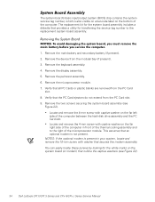
...palmrest assembly. 6. Remove the microprocessor module. 7. Remove the two screws securing the system board assembly (see Figure 22). 34 Dell Latitude CPt V/CPt S Series and CPx H/CPx J Series Service Manual Remove the display assembly. 5. Verify that an optional modem is present in front of the thermal cooling assembly...22). You can easily locate these screws by looking for the white marks on the far left side of the computer between the hard-disk drive assembly and the PC Card slot. NOTES: If the optional modem is not present. Remove the keyboard assembly. 4. Verify that...
...palmrest assembly. 6. Remove the microprocessor module. 7. Remove the two screws securing the system board assembly (see Figure 22). 34 Dell Latitude CPt V/CPt S Series and CPx H/CPx J Series Service Manual Remove the display assembly. 5. Verify that an optional modem is present in front of the thermal cooling assembly...22). You can easily locate these screws by looking for the white marks on the far left side of the computer between the hard-disk drive assembly and the PC Card slot. NOTES: If the optional modem is not present. Remove the keyboard assembly. 4. Verify that...
Service Manual
Page 47
hard-disk drive assembly removal, 11 reserve battery removal, 32 inverter, 12.1-inch LCD panel removal, 26 replacement, 27 keyboard assembly removal, 15 memory module removal, 13 memory ... bay devices removal, 12 module latch assemblies removal, 37 screw identification and tightening, 3 sockets memory module, 13 SuperDisk LS-120 drive removal, 12 system board assembly removal, 18 thermal cooling assembly removal, 36 tools, 2 travel module removal, 12 ZIF connectors, 5 palmrest assembly removal, 30 2 Dell Latitude CPt V/CPt S Series and CPx H/Cpx J Series Service Manual
hard-disk drive assembly removal, 11 reserve battery removal, 32 inverter, 12.1-inch LCD panel removal, 26 replacement, 27 keyboard assembly removal, 15 memory module removal, 13 memory ... bay devices removal, 12 module latch assemblies removal, 37 screw identification and tightening, 3 sockets memory module, 13 SuperDisk LS-120 drive removal, 12 system board assembly removal, 18 thermal cooling assembly removal, 36 tools, 2 travel module removal, 12 ZIF connectors, 5 palmrest assembly removal, 30 2 Dell Latitude CPt V/CPt S Series and CPx H/Cpx J Series Service Manual


