
Service Manual
Page 10
...reduce the potential for 4 seconds. 3. Remove any attached peripherals from the computer. 5. Remove any work in the modular device bay. 2 Dell Latitude CPt V/CPt S Series and CPx H/CPx J Series Service Manual Disconnect all open application programs. 2. Save any installed devices in progress and close all ... the PC Card slot. 7. Disconnect the computer and any installed PC Cards or plastic blanks from the computer. 6. NOTE: Make sure the computer is docked in this manual require the following tools: Number 1 magnetized Phillips-head screwdriver Small flat-blade screwdriver ...
...reduce the potential for 4 seconds. 3. Remove any attached peripherals from the computer. 5. Remove any work in the modular device bay. 2 Dell Latitude CPt V/CPt S Series and CPx H/CPx J Series Service Manual Disconnect all open application programs. 2. Save any installed devices in progress and close all ... the PC Card slot. 7. Disconnect the computer and any installed PC Cards or plastic blanks from the computer. 6. NOTE: Make sure the computer is docked in this manual require the following tools: Number 1 magnetized Phillips-head screwdriver Small flat-blade screwdriver ...
Service Manual
Page 13
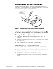
... force (ZIF) connectors. To ensure a firm connection, make sure the ZIF connector is completely closed. Push gently sideways on the movable part of the connector until it out of the connector. 1. While holding the cable in place, close the ZIF connector. support.dell.com Dell Latitude CPt V/CPt S Series and CPx H/CPx J Series Service Manual 5 Orient...
... force (ZIF) connectors. To ensure a firm connection, make sure the ZIF connector is completely closed. Push gently sideways on the movable part of the connector until it out of the connector. 1. While holding the cable in place, close the ZIF connector. support.dell.com Dell Latitude CPt V/CPt S Series and CPx H/CPx J Series Service Manual 5 Orient...

Service Manual
Page 32
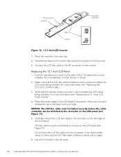
... on the left edge of the LCD panel. Place the bottom edge of the panel with your hand. 2. Carefully connect the LCD flex cable to make sure the LCD flex cable is aligned correctly and try again. 3. Reinstall the six 3-mm screws securing the LCD panel to reassemble the LCD panel... cover. 4. Do not force the LCD flex cable into the connector. Secure the right side first. 1. NOTE: Use a magnetic screwdriver to the top cover. 24 Dell Latitude CPt V/CPt S Series and CPx H/CPx J Series Service Manual
... on the left edge of the LCD panel. Place the bottom edge of the panel with your hand. 2. Carefully connect the LCD flex cable to make sure the LCD flex cable is aligned correctly and try again. 3. Reinstall the six 3-mm screws securing the LCD panel to reassemble the LCD panel... cover. 4. Do not force the LCD flex cable into the connector. Secure the right side first. 1. NOTE: Use a magnetic screwdriver to the top cover. 24 Dell Latitude CPt V/CPt S Series and CPx H/CPx J Series Service Manual

Service Manual
Page 35
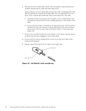
...installed. 2. Find the manufacturer's name on top) crease (underneath) To replace the 12.1-inch display LCD panel inverter, perform the following steps: 1. support.dell.com Dell Latitude CPt V/CPt S Series and CPx H/CPx J Series Service Manual 27 7. Fold for a Sharp LCD Panel curled back to connect to the cable. If you are...flex cable at the crease as shown in Figure 17, so that the name of the LCD panel that is either panel by making one fold to panel LCD manufacturer name Fold for more information. This means that the inverter's configuration jumpers are printed on the ...
...installed. 2. Find the manufacturer's name on top) crease (underneath) To replace the 12.1-inch display LCD panel inverter, perform the following steps: 1. support.dell.com Dell Latitude CPt V/CPt S Series and CPx H/CPx J Series Service Manual 27 7. Fold for a Sharp LCD Panel curled back to connect to the cable. If you are...flex cable at the crease as shown in Figure 17, so that the name of the LCD panel that is either panel by making one fold to panel LCD manufacturer name Fold for more information. This means that the inverter's configuration jumpers are printed on the ...
Service Manual
Page 36
Place the inverter in the top cover. 28 Dell Latitude CPt V/CPt S Series and CPx H/CPx J Series Service Manual Reinstall the three 3-mm screws that the inverter jumpers are set to the top cover. 5. Verify that secure ... ZIF connector on the left edge of the LCD panel. Find the manufacturer's name on the back of the panel with your hand. 5. Make sure that is to make sure the LCD flex cable is either Torisan or Sharp. 2. For more information see "Replacing the 12.1-Inch LCD Flex Cable." 3. The manufacturer...
Place the inverter in the top cover. 28 Dell Latitude CPt V/CPt S Series and CPx H/CPx J Series Service Manual Reinstall the three 3-mm screws that the inverter jumpers are set to the top cover. 5. Verify that secure ... ZIF connector on the left edge of the LCD panel. Find the manufacturer's name on the back of the panel with your hand. 5. Make sure that is to make sure the LCD flex cable is either Torisan or Sharp. 2. For more information see "Replacing the 12.1-Inch LCD Flex Cable." 3. The manufacturer...
Service Manual
Page 46
... fully engaged in the new latch button from the case: a. bumps (2) wear ribs (2) 38 Dell Latitude CPt V/CPt S Series and CPx H/CPx J Series Service Manual If the module latch assembly does come loose from the bottom of the base, making certain its respective hole, that the side of the latch with the two bumps is...
... fully engaged in the new latch button from the case: a. bumps (2) wear ribs (2) 38 Dell Latitude CPt V/CPt S Series and CPx H/CPx J Series Service Manual If the module latch assembly does come loose from the bottom of the base, making certain its respective hole, that the side of the latch with the two bumps is...


