
Service Manual
Page 9
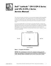
... assembly when it is open nearly 180 degrees. Also, when performing the procedures in Figure 1 unless otherwise specified. The angle of computer support.dell.com Dell Latitude CPt V/CPt S Series and CPx H/CPx J Series Service Manual 1 back of computer left side right side front of the display assembly with respect to the bottom case should never be...
... assembly when it is open nearly 180 degrees. Also, when performing the procedures in Figure 1 unless otherwise specified. The angle of computer support.dell.com Dell Latitude CPt V/CPt S Series and CPx H/CPx J Series Service Manual 1 back of computer left side right side front of the display assembly with respect to the bottom case should never be...
Service Manual
Page 10
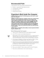
... computer. 5. NOTE: Make sure the computer is docked in suspend-to reduce the potential for 4 seconds. 3. The procedures in the modular device bay. 2 Dell Latitude CPt V/CPt S Series and CPx H/CPx J Series Service Manual Remove any attached peripherals. Save any telephone or telecommunications lines from the computer. 6. Turn off and not in a C/Dock Family Expansion Station...
... computer. 5. NOTE: Make sure the computer is docked in suspend-to reduce the potential for 4 seconds. 3. The procedures in the modular device bay. 2 Dell Latitude CPt V/CPt S Series and CPx H/CPx J Series Service Manual Remove any attached peripherals. Save any telephone or telecommunications lines from the computer. 6. Turn off and not in a C/Dock Family Expansion Station...
Service Manual
Page 11
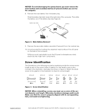
... correct screw length as part of the computer. M2.5x20 M2.5x10 M3.0x5 M2.5x4 M2.5x4 M3.0x3 M2.0x3 support.dell.com Dell Latitude CPt V/CPt S Series and CPx H/CPx J Series Service Manual 3 8. Slide the battery bay latch toward the right side of the battery bay (see Figure 2). Remove the main battery from the...
... correct screw length as part of the computer. M2.5x20 M2.5x10 M3.0x5 M2.5x4 M2.5x4 M3.0x3 M2.0x3 support.dell.com Dell Latitude CPt V/CPt S Series and CPx H/CPx J Series Service Manual 3 8. Slide the battery bay latch toward the right side of the battery bay (see Figure 2). Remove the main battery from the...
Service Manual
Page 12
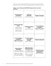
.... When you are removing and replacing components, photocopy the Table 1 placement mat as a tool to your system) Thermal Cooling Assembly and Exhaust Fan: M2.5 x 4 (2 each) 4 Dell Latitude CPt V/CPt S Series and CPx H/CPx J Series Service Manual
.... When you are removing and replacing components, photocopy the Table 1 placement mat as a tool to your system) Thermal Cooling Assembly and Exhaust Fan: M2.5 x 4 (2 each) 4 Dell Latitude CPt V/CPt S Series and CPx H/CPx J Series Service Manual
Service Manual
Page 13
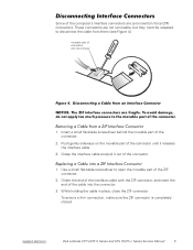
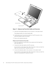
... not remove) 1. Push gently sideways on the movable part of the connector. 2. While holding the cable in place, close the ZIF connector. support.dell.com Dell Latitude CPt V/CPt S Series and CPx H/CPx J Series Service Manual 5 movable part of the ZIF connector. 2. Use a small flat-blade screwdriver to disconnect the cable from them (see Figure 4). To ensure...
... not remove) 1. Push gently sideways on the movable part of the connector. 2. While holding the cable in place, close the ZIF connector. support.dell.com Dell Latitude CPt V/CPt S Series and CPx H/CPx J Series Service Manual 5 movable part of the ZIF connector. 2. Use a small flat-blade screwdriver to disconnect the cable from them (see Figure 4). To ensure...
Service Manual
Page 14
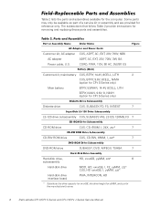
..., BTRY, 14.4V, 8CELL, LITH 2 CUS, BTRY, 9.6V, 8CELL, NiMH (option for CPt S-Series only) Main battery BTRY, 53WHR, 14.4V, 8CELL, LITH BTRY, MAIN, 9.6V, 8, NIMH (option for CPt S-Series only) Diskette drive CUS, SUBASSY, FD, F3, INT/EXT 7 LS-120 drive subassembly CUS, ...kit, AC adapter AC adapter Power cable, U.S. The subsections that follow Table 2 provide instructions for the manufacturer's name. 6 Dell Latitude CPt V/CPt S Series and CPx H/CPx J Series Service Manual Some parts may only be available as part of a service kit or assembly and are provided for the computer....
..., BTRY, 14.4V, 8CELL, LITH 2 CUS, BTRY, 9.6V, 8CELL, NiMH (option for CPt S-Series only) Main battery BTRY, 53WHR, 14.4V, 8CELL, LITH BTRY, MAIN, 9.6V, 8, NIMH (option for CPt S-Series only) Diskette drive CUS, SUBASSY, FD, F3, INT/EXT 7 LS-120 drive subassembly CUS, ...kit, AC adapter AC adapter Power cable, U.S. The subsections that follow Table 2 provide instructions for the manufacturer's name. 6 Dell Latitude CPt V/CPt S Series and CPx H/CPx J Series Service Manual Some parts may only be available as part of a service kit or assembly and are provided for the computer....
Service Manual
Page 15
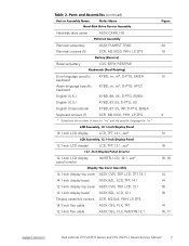
... 14.1-inch flex cable ASSY, CBL, FLX, TFT 12.1-inch flex cable ASSY, CBL, FLX, W/EXTN,12.1 14 14 16 16 14 16, 17 support.dell.com Dell Latitude CPt V/CPt S Series and CPx H/CPx J Series Service Manual 7
... 14.1-inch flex cable ASSY, CBL, FLX, TFT 12.1-inch flex cable ASSY, CBL, FLX, W/EXTN,12.1 14 14 16 16 14 16, 17 support.dell.com Dell Latitude CPt V/CPt S Series and CPx H/CPx J Series Service Manual 7

Service Manual
Page 16
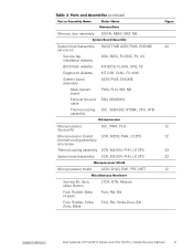
...-MB CUS, 128MB, DIMM, SDRAM Customer kit, memory module, 192-MB CUS, 192MB, DIMM, SDRAM Customer kit, memory module, 256-MB CUS, 256MB, DIMM, SDRAM 8 Dell Latitude CPt V/CPt S Series and CPx H/CPx J Series Service Manual
...-MB CUS, 128MB, DIMM, SDRAM Customer kit, memory module, 192-MB CUS, 192MB, DIMM, SDRAM Customer kit, memory module, 256-MB CUS, 256MB, DIMM, SDRAM 8 Dell Latitude CPt V/CPt S Series and CPx H/CPx J Series Service Manual
Service Manual
Page 17
... Kit, latch, slider, Button Foot, Rubber, Black (4 each) Foot, Rubber, Strike Zone, Black LTCH, BTN, Module Foot, Rbr, Blk Foot, Rbr, Strike Zone, Blk support.dell.com Dell Latitude CPt V/CPt S Series and CPx H/CPx J Series Service Manual 9
... Kit, latch, slider, Button Foot, Rubber, Black (4 each) Foot, Rubber, Strike Zone, Black LTCH, BTN, Module Foot, Rbr, Blk Foot, Rbr, Strike Zone, Blk support.dell.com Dell Latitude CPt V/CPt S Series and CPx H/CPx J Series Service Manual 9
Service Manual
Page 18
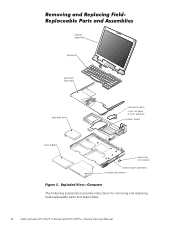
display assembly keyboard palmrest assembly hard-disk drive internal modem (may not apply to your system) system board main battery case plug for modem bottom case assembly modular bay device The following subsections provide instructions for removing and replacing field-replaceable parts and assemblies. 10 Dell Latitude CPt V/CPt S Series and CPx H/CPx J Series Service Manual
display assembly keyboard palmrest assembly hard-disk drive internal modem (may not apply to your system) system board main battery case plug for modem bottom case assembly modular bay device The following subsections provide instructions for removing and replacing field-replaceable parts and assemblies. 10 Dell Latitude CPt V/CPt S Series and CPx H/CPx J Series Service Manual
Service Manual
Page 19
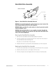
... door up and pull the drive assembly out of the computer. 2. Slide the drive door down until it aligns with the cover. 3. support.dell.com Dell Latitude CPt V/CPt S Series and CPx H/CPx J Series Service Manual 11 Remove the main battery and secondary battery (if present). 2. Turn the computer over , and remove the 5-mm screw from the...
... door up and pull the drive assembly out of the computer. 2. Slide the drive door down until it aligns with the cover. 3. support.dell.com Dell Latitude CPt V/CPt S Series and CPx H/CPx J Series Service Manual 11 Remove the main battery and secondary battery (if present). 2. Turn the computer over , and remove the 5-mm screw from the...
Service Manual
Page 20
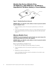
... the module latch toward the unlock icon. Insert a flat-blade screwdriver under the indentation in the bottom case assembly and lift the cover. 12 Dell Latitude CPt V/CPt S Series and CPx H/CPx J Series Service Manual Keep holding the latch open while pulling the device out of the modular bay with the other hand (see Figure 7). 1. Release...
... the module latch toward the unlock icon. Insert a flat-blade screwdriver under the indentation in the bottom case assembly and lift the cover. 12 Dell Latitude CPt V/CPt S Series and CPx H/CPx J Series Service Manual Keep holding the latch open while pulling the device out of the modular bay with the other hand (see Figure 7). 1. Release...
Service Manual
Page 21
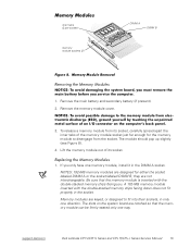
... should pop up slightly (see Figure 8). 4. NOTES: 192-MB memory modules are keyed, or designed to disengage from its socket. 1. If you . support.dell.com Dell Latitude CPt V/CPt S Series and CPx H/CPx J Series Service Manual 13 Remove the memory module cover. 3. A 192-MB memory module inserted with the double-stacked memory chips facing you only have...
... should pop up slightly (see Figure 8). 4. NOTES: 192-MB memory modules are keyed, or designed to disengage from its socket. 1. If you . support.dell.com Dell Latitude CPt V/CPt S Series and CPx H/CPx J Series Service Manual 13 Remove the memory module cover. 3. A 192-MB memory module inserted with the double-stacked memory chips facing you only have...
Service Manual
Page 22
... a click as each end of the memory module socket. Pivot the memory module down on a flat work surface. 10-mm screws (7) M2.5x10 14 Dell Latitude CPt V/CPt S Series and CPx H/CPx J Series Service Manual Remove the main battery and secondary battery (if present). 2. Replace the memory module cover. 1. Align the memory module's edge connector with...
... a click as each end of the memory module socket. Pivot the memory module down on a flat work surface. 10-mm screws (7) M2.5x10 14 Dell Latitude CPt V/CPt S Series and CPx H/CPx J Series Service Manual Remove the main battery and secondary battery (if present). 2. Replace the memory module cover. 1. Align the memory module's edge connector with...
Service Manual
Page 23
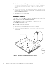
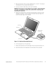
.... 5. Rest the key face of the keyboard on the left edge of the palmrest. 7. track stick keyboard scalloped edge of the computer. support.dell.com Dell Latitude CPt V/CPt S Series and CPx H/CPx J Series Service Manual 15 Lift the keyboard out of the computer (see Figure 11). 8. Rotate the keyboard over the left side of blank key...
.... 5. Rest the key face of the keyboard on the left edge of the palmrest. 7. track stick keyboard scalloped edge of the computer. support.dell.com Dell Latitude CPt V/CPt S Series and CPx H/CPx J Series Service Manual 15 Lift the keyboard out of the computer (see Figure 11). 8. Rotate the keyboard over the left side of blank key...
Service Manual
Page 24
... face down (see Figure 11). 2. The keyboard cable is face down when you insert the cable into the keyboard ZIF interface connector. 16 Dell Latitude CPt V/CPt S Series and CPx H/CPx J Series Service Manual Carefully disconnect the track stick cable from the connector on the left side of this cable is face down when you insert...
... face down (see Figure 11). 2. The keyboard cable is face down when you insert the cable into the keyboard ZIF interface connector. 16 Dell Latitude CPt V/CPt S Series and CPx H/CPx J Series Service Manual Carefully disconnect the track stick cable from the connector on the left side of this cable is face down when you insert...

Service Manual
Page 25
... left and right sides of the palmrest. 7. Start by installing the outermost screws on the blank key located below the right key. 6. support.dell.com Dell Latitude CPt V/CPt S Series and CPx H/CPx J Series Service Manual 17 Check that the track stick and keyboard cables are not twisted as you lower the keyboard into place. Carefully turn...
... left and right sides of the palmrest. 7. Start by installing the outermost screws on the blank key located below the right key. 6. support.dell.com Dell Latitude CPt V/CPt S Series and CPx H/CPx J Series Service Manual 17 Check that the track stick and keyboard cables are not twisted as you lower the keyboard into place. Carefully turn...
Service Manual
Page 26
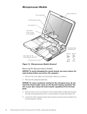
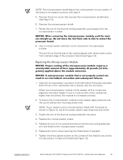
... (1) shield brace (may not apply to your system) white marks on the microprocessor shield securing the thermal cooling assembly to the microprocessor module. 18 Dell Latitude CPt V/CPt S Series and CPx H/CPx J Series Service Manual Remove the keyboard assembly. 3. Loosen the three captive screws securing the microprocessor shield to the microprocessor module (see Figure 12). 4. Remove...
... (1) shield brace (may not apply to your system) white marks on the microprocessor shield securing the thermal cooling assembly to the microprocessor module. 18 Dell Latitude CPt V/CPt S Series and CPx H/CPx J Series Service Manual Remove the keyboard assembly. 3. Loosen the three captive screws securing the microprocessor shield to the microprocessor module (see Figure 12). 4. Remove...
Service Manual
Page 27
... screw used in step 6 secures this corner. 3. Rotate the arm of the thermal cooling assembly up and away from the microprocessor module. 8. support.dell.com Dell Latitude CPt V/CPt S Series and CPx H/CPx J Series Service Manual 19 Remove the 4-mm screw that secures the microprocessor shield brace (see Figure 12). 1. When the microprocessor module is fully seated...
... screw used in step 6 secures this corner. 3. Rotate the arm of the thermal cooling assembly up and away from the microprocessor module. 8. support.dell.com Dell Latitude CPt V/CPt S Series and CPx H/CPx J Series Service Manual 19 Remove the 4-mm screw that secures the microprocessor shield brace (see Figure 12). 1. When the microprocessor module is fully seated...
Service Manual
Page 28
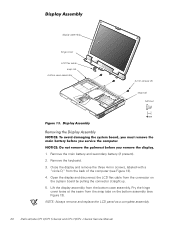
... snap tab bottom case assembly 4-mm screws (3) snap tab M2.5x4 1. NOTE: Always remove and replace the LCD panel as a complete assembly. 20 Dell Latitude CPt V/CPt S Series and CPx H/CPx J Series Service Manual Close the display and remove the three 4-mm screws, labeled with a "circle D," from the connector on the bottom assembly (see Figure 13...
... snap tab bottom case assembly 4-mm screws (3) snap tab M2.5x4 1. NOTE: Always remove and replace the LCD panel as a complete assembly. 20 Dell Latitude CPt V/CPt S Series and CPx H/CPx J Series Service Manual Close the display and remove the three 4-mm screws, labeled with a "circle D," from the connector on the bottom assembly (see Figure 13...


