Service Manual
Page 3
... 1-4 Drive Activity Indicator 1-4 Battery Indicator 1-4 Keyboard Indicators 1-5 Controlling Computer Power 1-5 Interrupt Assignments 1-6 Technical Specifications 1-7 Initial User Contact 2-1 Visual Inspection 2-2 Observing the Boot Routine 2-4 Eliminating Resource Conflicts 2-6 Getting Help 2-6 POST Error Codes 3-1 Battery Failure Codes 3-4 System Error Messages 3-5 Running the Dell Diagnostics 3-9 Recommended Tools 4-2 Precautionary Measures 4-2 Screw Identification and Tightening 4-3 ZIF Connectors 4-4 Field...
... 1-4 Drive Activity Indicator 1-4 Battery Indicator 1-4 Keyboard Indicators 1-5 Controlling Computer Power 1-5 Interrupt Assignments 1-6 Technical Specifications 1-7 Initial User Contact 2-1 Visual Inspection 2-2 Observing the Boot Routine 2-4 Eliminating Resource Conflicts 2-6 Getting Help 2-6 POST Error Codes 3-1 Battery Failure Codes 3-4 System Error Messages 3-5 Running the Dell Diagnostics 3-9 Recommended Tools 4-2 Precautionary Measures 4-2 Screw Identification and Tightening 4-3 ZIF Connectors 4-4 Field...
Service Manual
Page 4
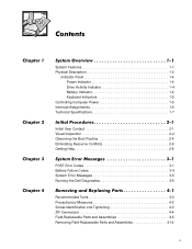
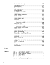
... Drive Assembly 4-15 Memory Module Cover 4-16 Memory Modules 4-17 Keyboard Assembly 4-18 Back Cover Assembly 4-20 Palmrest Assembly 4-21 Touch-Pad Interface Module 4-23 Power Button 4-24 Display Assembly Components 4-25 Display Assembly 4-27 Display Assembly Bezel 4-29 Display Assembly Latch 4-30 LCD Panel 4-31 12.1-Inch LCD Displays 4-31...
... Drive Assembly 4-15 Memory Module Cover 4-16 Memory Modules 4-17 Keyboard Assembly 4-18 Back Cover Assembly 4-20 Palmrest Assembly 4-21 Touch-Pad Interface Module 4-23 Power Button 4-24 Display Assembly Components 4-25 Display Assembly 4-27 Display Assembly Bezel 4-29 Display Assembly Latch 4-30 LCD Panel 4-31 12.1-Inch LCD Displays 4-31...
Service Manual
Page 8
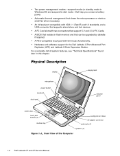
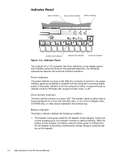
... 3.3-V PC Cards. A PC Card slot with full mouse functionality. display microphone power button keyboard touch pad battery bay touch pad buttons (2) modular bay display latch indicator panel cooling-fan air intake AC adapter connector audio jacks (3) speakers (2) 1-2 Dell Latitude CP and CPi Service Manual A PS/2-compatible touch pad with two connectors that supports stand...
... 3.3-V PC Cards. A PC Card slot with full mouse functionality. display microphone power button keyboard touch pad battery bay touch pad buttons (2) modular bay display latch indicator panel cooling-fan air intake AC adapter connector audio jacks (3) speakers (2) 1-2 Dell Latitude CP and CPi Service Manual A PS/2-compatible touch pad with two connectors that supports stand...
Service Manual
Page 10
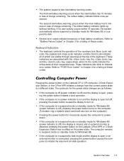
... standby mode for Windows 98), suspend-to keep the battery at full capacity. 1-4 Dell Latitude CP and CPi Service Manual The battery indicator displays the following subsections describe the functions of these indicators. After the computer is turned on, the power indicator lights up when data is being transferred to or from the hard...
... standby mode for Windows 98), suspend-to keep the battery at full capacity. 1-4 Dell Latitude CP and CPi Service Manual The battery indicator displays the following subsections describe the functions of these indicators. After the computer is turned on, the power indicator lights up when data is being transferred to or from the hard...
Service Manual
Page 11
... conditions. If the computer is in Chapter 3 for the power state changes are as follows: If the computer is off (power indicator is off ), pressing the power button turns on the computer. (A modem ring or system alarm event will also turn on the Latitude CP or CPi computer, C/Dock Expansion Station, or the C/Port APR...
... conditions. If the computer is in Chapter 3 for the power state changes are as follows: If the computer is off (power indicator is off ), pressing the power button turns on the computer. (A modem ring or system alarm event will also turn on the Latitude CP or CPi computer, C/Dock Expansion Station, or the C/Port APR...
Service Manual
Page 16
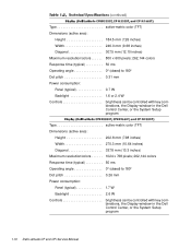
...angle 0° (closed) to 180° Dot pitch 0.31 mm Power consumption: Panel (typical 0.7 W Backlight 1.6 or 2.4 W Controls brightness can be controlled with key combinations, the Display window in the Dell Control Center, or the System Setup program Type active-matrix color (... angle 0° (closed) to 180° Dot pitch 0.26 mm Power consumption: Panel (typical 1.7 W Backlight 2.6 W Controls brightness can be controlled with key combinations, the Display window in the Dell Control Center, or the System Setup program 1-10 Dell Latitude CP and CPi Service Manual
...angle 0° (closed) to 180° Dot pitch 0.31 mm Power consumption: Panel (typical 0.7 W Backlight 1.6 or 2.4 W Controls brightness can be controlled with key combinations, the Display window in the Dell Control Center, or the System Setup program Type active-matrix color (... angle 0° (closed) to 180° Dot pitch 0.26 mm Power consumption: Panel (typical 1.7 W Backlight 2.6 W Controls brightness can be controlled with key combinations, the Display window in the Dell Control Center, or the System Setup program 1-10 Dell Latitude CP and CPi Service Manual
Service Manual
Page 17
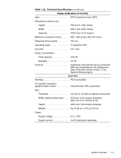
... ms Operating angle 0° (closed) to 180° Dot pitch 0.31 mm Power consumption: Panel (typical 0.63 W Backlight 3.2 W Controls brightness and contrast can be controlled with key combinations, the Display window in the Dell Control Center, or the System Setup program Interface PS/2-compatible X/Y position resolution (graphics .... 61.8 mm (2.43 inches) at bottom; 58.6 mm (2.31 inches) at top Height 48.8-mm (1.92-inches) rectangle Weight 8 g (0.28 oz) ± 0.5 g (0.02 oz) Power: Supply voltage 5 V ± 10% Supply current 4 mA (maximum operating) System Overview 1-11
... ms Operating angle 0° (closed) to 180° Dot pitch 0.31 mm Power consumption: Panel (typical 0.63 W Backlight 3.2 W Controls brightness and contrast can be controlled with key combinations, the Display window in the Dell Control Center, or the System Setup program Interface PS/2-compatible X/Y position resolution (graphics .... 61.8 mm (2.43 inches) at bottom; 58.6 mm (2.31 inches) at top Height 48.8-mm (1.92-inches) rectangle Weight 8 g (0.28 oz) ± 0.5 g (0.02 oz) Power: Supply voltage 5 V ± 10% Supply current 4 mA (maximum operating) System Overview 1-11
Service Manual
Page 22
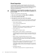
... down the operating system; A temporary battery failure has occurred. Press the power button for the Microsoft Windows 98 operating system) or suspend-to -disk mode. 2-2 Dell Latitude CP and CPi Service Manual The computer is either off . An error occurred during system POST. Power indicator is on state. All indicators remain off or in the...
... down the operating system; A temporary battery failure has occurred. Press the power button for the Microsoft Windows 98 operating system) or suspend-to -disk mode. 2-2 Dell Latitude CP and CPi Service Manual The computer is either off . An error occurred during system POST. Power indicator is on state. All indicators remain off or in the...
Service Manual
Page 23
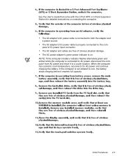
...the battery stops charging before it to both the adapter and a power source. Initial Procedures 2-3 The AC adapter and cables are free of obvious physical damage. If the computer is properly connected to AC power and continue charging the battery. When the computer has cooled to room... temperature, reconnect it to the computer's DC power input connector. The AC power adapter's green power indicator is connected to a cooler location. See the User's Guide that came with the C/Port APR or C/Dock Expansion Station...
...the battery stops charging before it to both the adapter and a power source. Initial Procedures 2-3 The AC adapter and cables are free of obvious physical damage. If the computer is properly connected to AC power and continue charging the battery. When the computer has cooled to room... temperature, reconnect it to the computer's DC power input connector. The AC power adapter's green power indicator is connected to a cooler location. See the User's Guide that came with the C/Port APR or C/Dock Expansion Station...
Service Manual
Page 24
... to ensure a firm connection. Does the problem reoccur? The attached device and its interface cable are secure enough to a power source and free of the Dell Latitude CP Reference and Troubleshooting Guide. 2-4 Dell Latitude CP and CPi Service Manual No. The captive screws that users make copies of the diagnostics diskette and, while the boot routine...
... to ensure a firm connection. Does the problem reoccur? The attached device and its interface cable are secure enough to a power source and free of the Dell Latitude CP Reference and Troubleshooting Guide. 2-4 Dell Latitude CP and CPi Service Manual No. The captive screws that users make copies of the diagnostics diskette and, while the boot routine...
Service Manual
Page 25
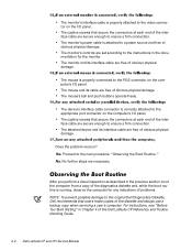
Troubleshoot the power subsystem. If the indicator fails to light during the boot routine, refer to Table 3-1. These messages can indicate problems or provide status information. Proceed to the next section, "Eliminating Resource Conflicts." See "Running the Dell Diagnostics" in Chapter 3. To observe the boot routine,...battery indicator flashes alternately green and amber, or flashes amber four times per second, refer to Table 3-2. See "Running the Dell Diagnostics" in Chapter 3. No. No. Battery failure codes - Error codes - System error messages - Drive access indicator -
Troubleshoot the power subsystem. If the indicator fails to light during the boot routine, refer to Table 3-1. These messages can indicate problems or provide status information. Proceed to the next section, "Eliminating Resource Conflicts." See "Running the Dell Diagnostics" in Chapter 3. To observe the boot routine,...battery indicator flashes alternately green and amber, or flashes amber four times per second, refer to Table 3-2. See "Running the Dell Diagnostics" in Chapter 3. No. No. Battery failure codes - Error codes - System error messages - Drive access indicator -
Service Manual
Page 35
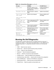
...in protected mode Warning! Tests the CD-ROM drive subsystem Serial/Infrared Ports - Seek error Shutdown failure Time-of-day clock lost power MS-DOS unable to System board faulty. Battery is running out of -day not set-please run the System Setup program. ...subsystem Mouse - System clock stopped. Timer chip counter 2 failed Unexpected interrupt in troubleshooting the computer. If needed, see Chapter 4, "Running the Dell Diagnostics," in RTC does not match system clock. Tests the serial communication port Parallel Ports - Tests the IDE hard-disk drive subsystem IDE CD...
...in protected mode Warning! Tests the CD-ROM drive subsystem Serial/Infrared Ports - Seek error Shutdown failure Time-of-day clock lost power MS-DOS unable to System board faulty. Battery is running out of -day not set-please run the System Setup program. ...subsystem Mouse - System clock stopped. Timer chip counter 2 failed Unexpected interrupt in troubleshooting the computer. If needed, see Chapter 4, "Running the Dell Diagnostics," in RTC does not match system clock. Tests the serial communication port Parallel Ports - Tests the IDE hard-disk drive subsystem IDE CD...

Service Manual
Page 38
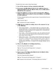
Most of the procedures in this guide require the use of one or more of the following steps: NOTE: Make sure the computer is turned off and not in suspend-to-disk mode. If you start to work on the computer, perform the following tools: Number 1 magnetized Phillips-head screwdriver Small flat-blade screwdriver Small plastic scribe Before you cannot shut down the computer using the computer's operating system, press the power button for 4 seconds. 4-2 Dell Latitude CP and CPi Service Manual
Most of the procedures in this guide require the use of one or more of the following steps: NOTE: Make sure the computer is turned off and not in suspend-to-disk mode. If you start to work on the computer, perform the following tools: Number 1 magnetized Phillips-head screwdriver Small flat-blade screwdriver Small plastic scribe Before you cannot shut down the computer using the computer's operating system, press the power button for 4 seconds. 4-2 Dell Latitude CP and CPi Service Manual
Service Manual
Page 41
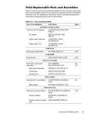
Customer kit, AC adapter AC adapter Power cable, Australia Power cable, U.S. The subsections that follow Table 4-1 provide instructions for reference only. CUS,ADPT,AC,EXT,20V,70W, NBK,CP ADPT,AC,EXT,20V,70W, NBK,...
Customer kit, AC adapter AC adapter Power cable, Australia Power cable, U.S. The subsections that follow Table 4-1 provide instructions for reference only. CUS,ADPT,AC,EXT,20V,70W, NBK,CP ADPT,AC,EXT,20V,70W, NBK,...
Service Manual
Page 47
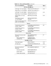
...,TPAD,CP 4-13 GDE,INTK,AIR,FAN,PLSTC,CP 4-30 Service kit, palmrest SVC,SUBASSY,PLMRST,CP 4-12 assembly Palmrest assembly ASSY,PLMRST,GRY,CP Power button SWT,PWR SW, CP Power button spring SPR,PWR SW,CP Removing and Replacing Parts 4-11
...,TPAD,CP 4-13 GDE,INTK,AIR,FAN,PLSTC,CP 4-30 Service kit, palmrest SVC,SUBASSY,PLMRST,CP 4-12 assembly Palmrest assembly ASSY,PLMRST,GRY,CP Power button SWT,PWR SW, CP Power button spring SPR,PWR SW,CP Removing and Replacing Parts 4-11

Service Manual
Page 67
The following subsections describe how to remove an LCD panel. upper-left corner interface cable connector 5-mm screws (4) LCD panel LCD panel power cable interface cable connector J2 LCD inverter board display-assembly top cover Removing and Replacing Parts 4-31
The following subsections describe how to remove an LCD panel. upper-left corner interface cable connector 5-mm screws (4) LCD panel LCD panel power cable interface cable connector J2 LCD inverter board display-assembly top cover Removing and Replacing Parts 4-31

Service Manual
Page 68
NOTE: When replacing the LCD panel, ensure that the tabs on the display-assembly EMI shield fit over the four LCD panel mounting bosses. (This is necessary for adequate grounding of the LCD panel.) 5-mm screws (4) LCD panel interface cable magnet holder interface cable connector LCD inverter board LCD panel power cable display-assembly top cover LCD inverter board shield 4-32 Dell Latitude CP and CPi Service Manual
NOTE: When replacing the LCD panel, ensure that the tabs on the display-assembly EMI shield fit over the four LCD panel mounting bosses. (This is necessary for adequate grounding of the LCD panel.) 5-mm screws (4) LCD panel interface cable magnet holder interface cable connector LCD inverter board LCD panel power cable display-assembly top cover LCD inverter board shield 4-32 Dell Latitude CP and CPi Service Manual

Service Manual
Page 71
...to remove an LCD inverter board from a 12.1-inch or 13.3-inch LCD display. display-assembly top cover connector J2 5-mm screws (2) spacer (2) LCD-assembly power cable LCD inverter board connector J1 Note the placement of the EMI shield over the lower screw boss, and the routing of the LCD-panel... power cable around the plastic screw bosses in the display-assembly top cover. The following subsections describe how to securing the board in the display-...
...to remove an LCD inverter board from a 12.1-inch or 13.3-inch LCD display. display-assembly top cover connector J2 5-mm screws (2) spacer (2) LCD-assembly power cable LCD inverter board connector J1 Note the placement of the EMI shield over the lower screw boss, and the routing of the LCD-panel... power cable around the plastic screw bosses in the display-assembly top cover. The following subsections describe how to securing the board in the display-...

Service Manual
Page 86
exhaust fan power cable connector (JFAN1) 12-mm screws (2) exhaust fan NOTE: When replacing the exhaust fan, orient the fan such that the fan label faces outward and the power cable is at the upper right corner of the fan (when viewed from the back of the computer). (This will prevent the fan wires from being pinched when you reassemble the computer.) Make sure that the wires are routed below the upper EMI shield. 4-50 Dell Latitude CP and CPi Service Manual
exhaust fan power cable connector (JFAN1) 12-mm screws (2) exhaust fan NOTE: When replacing the exhaust fan, orient the fan such that the fan label faces outward and the power cable is at the upper right corner of the fan (when viewed from the back of the computer). (This will prevent the fan wires from being pinched when you reassemble the computer.) Make sure that the wires are routed below the upper EMI shield. 4-50 Dell Latitude CP and CPi Service Manual
Service Manual
Page 89
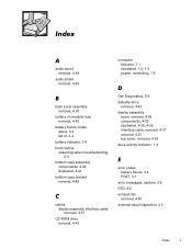
audio board removal, 4-44 audio shield removal, 4-43 computer features, 1-1 illustrated, 1-2, 1-3 power, controlling, 1-5 back cover assembly removal, 4-20 battery (in modular bay) removal, 4-42 battery failure codes about, 3-4 list of, 3-4 battery ... bottom case assembly components, 4-40 illustrated, 4-41 bottom case bracket removal, 4-45 cables display-assembly interface cable, removal, 4-37 CD-ROM drive removal, 4-42 Dell Diagnostics, 3-9 diskette drive removal, 4-42 display assembly bezel, removal, 4-29 components, 4-25 illustrated, 4-25, 4-26 interface cable, removal, 4-37 removal, 4-...
audio board removal, 4-44 audio shield removal, 4-43 computer features, 1-1 illustrated, 1-2, 1-3 power, controlling, 1-5 back cover assembly removal, 4-20 battery (in modular bay) removal, 4-42 battery failure codes about, 3-4 list of, 3-4 battery ... bottom case assembly components, 4-40 illustrated, 4-41 bottom case bracket removal, 4-45 cables display-assembly interface cable, removal, 4-37 CD-ROM drive removal, 4-42 Dell Diagnostics, 3-9 diskette drive removal, 4-42 display assembly bezel, removal, 4-29 components, 4-25 illustrated, 4-25, 4-26 interface cable, removal, 4-37 removal, 4-...


