User Manual
Page 3
... Computer 2 Screw Identification and Tightening 3 ZIF Connectors 4 Field-Replaceable Parts and Assemblies 5 Removing Field-Replaceable Parts and Assemblies 12 Hard-Disk Drive Assembly 13 Memory Module Cover 14 Memory Modules 15 Keyboard Assembly 16 Back Cover Assembly 18 Palmrest Assembly 19 Touch-Pad Interface Module... LCD Displays 26 LCD Display Hinge 28 Display-Assembly Top Cover 28 Bottom Case Assembly 28 Modular Bay Devices (Diskette Drive, CD-ROM Drive, Battery, or Travel Module 30 Audio Shield 30 Audio Board 31 Bottom Case Bracket 32 Module Latch Assemblies 33 Speakers...
... Computer 2 Screw Identification and Tightening 3 ZIF Connectors 4 Field-Replaceable Parts and Assemblies 5 Removing Field-Replaceable Parts and Assemblies 12 Hard-Disk Drive Assembly 13 Memory Module Cover 14 Memory Modules 15 Keyboard Assembly 16 Back Cover Assembly 18 Palmrest Assembly 19 Touch-Pad Interface Module... LCD Displays 26 LCD Display Hinge 28 Display-Assembly Top Cover 28 Bottom Case Assembly 28 Modular Bay Devices (Diskette Drive, CD-ROM Drive, Battery, or Travel Module 30 Audio Shield 30 Audio Board 31 Bottom Case Bracket 32 Module Latch Assemblies 33 Speakers...
User Manual
Page 4
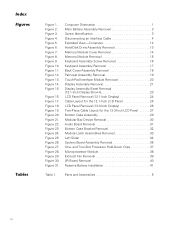
.... Figure 16. Figure 19. Figure 20. Figure 22. Computer Orientation 1 Main Battery Assembly Removal 3 Screw Identification 3 Disconnecting an Interface Cable 4 Exploded View-Computer 12 Hard-Disk Drive Assembly Removal 13 Memory Module Cover Removal 14 Memory Module Removal 15 Keyboard Assembly Screw Removal 16 Keyboard Assembly Removal 17 Back Cover Assembly Removal...
.... Figure 16. Figure 19. Figure 20. Figure 22. Computer Orientation 1 Main Battery Assembly Removal 3 Screw Identification 3 Disconnecting an Interface Cable 4 Exploded View-Computer 12 Hard-Disk Drive Assembly Removal 13 Memory Module Cover Removal 14 Memory Module Removal 15 Keyboard Assembly Screw Removal 16 Keyboard Assembly Removal 17 Back Cover Assembly Removal...
User Manual
Page 13
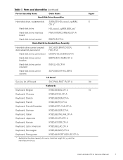
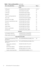
Dell Latitude CPi A Service Manual 7 Hard-disk drive, subassembly SUBASSY,HD,xxxxx,I,yyyMM, 6 CPi A* Hard-disk drive HD,xxxxx,I,yyMM,NBK,zzz* Hard-disk drive interface board PWA,INTERCONN,HD,CPi A Hard-disk drive bracket BRKT,HD,CPi A Hard-disk drive carrier bracket/ SVC,ASSY,BRKT/DOOR, 6 door assembly service kit HD,CPi A Hard-disk drive carrier door DOOR,HD,12.5MM,CPi A Hard-disk drive carrier bracket BRKT,HD,12.5MM,CPi A Hard-disk...
Dell Latitude CPi A Service Manual 7 Hard-disk drive, subassembly SUBASSY,HD,xxxxx,I,yyyMM, 6 CPi A* Hard-disk drive HD,xxxxx,I,yyMM,NBK,zzz* Hard-disk drive interface board PWA,INTERCONN,HD,CPi A Hard-disk drive bracket BRKT,HD,CPi A Hard-disk drive carrier bracket/ SVC,ASSY,BRKT/DOOR, 6 door assembly service kit HD,CPi A Hard-disk drive carrier door DOOR,HD,12.5MM,CPi A Hard-disk drive carrier bracket BRKT,HD,12.5MM,CPi A Hard-disk...
User Manual
Page 16
LCD panel LCD hinge LCD bezel Keyboard Thermal cooling assembly Touch pad Palmrest, front edge Palmrest, hard-disk drive area I/R board Back cover Audio board Bottom-case bracket Exhaust fan SCR,M2X4.5,PHH,LP,ZPS SCR,M3X5,PHH,LP,ZPS SCR,M2X4.5,PHH,LP,.../PWA,ENGINE,CPi A 26 service kit System board assembly, CPi A, SVC,ASSY,PRM/PWA,ENGINE,CPi A service kit Service tag installation diskette DSK,BIOS,FLDSVC,F3,US,CP BIOS flash diskette KIT,BIOS,FLASH,UPG,F3,CP Diagnostic diskette KIT,DSK,DIAG,F3,CPi A,WW System board assembly ASSY,PRM/PWA,ENGINE, CPi A 10 Dell Latitude CPi A Service...
LCD panel LCD hinge LCD bezel Keyboard Thermal cooling assembly Touch pad Palmrest, front edge Palmrest, hard-disk drive area I/R board Back cover Audio board Bottom-case bracket Exhaust fan SCR,M2X4.5,PHH,LP,ZPS SCR,M3X5,PHH,LP,ZPS SCR,M2X4.5,PHH,LP,.../PWA,ENGINE,CPi A 26 service kit System board assembly, CPi A, SVC,ASSY,PRM/PWA,ENGINE,CPi A service kit Service tag installation diskette DSK,BIOS,FLDSVC,F3,US,CP BIOS flash diskette KIT,BIOS,FLASH,UPG,F3,CP Diagnostic diskette KIT,DSK,DIAG,F3,CPi A,WW System board assembly ASSY,PRM/PWA,ENGINE, CPi A 10 Dell Latitude CPi A Service...
User Manual
Page 19
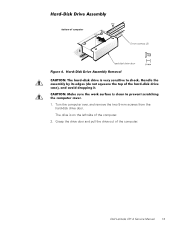
Grasp the drive door and pull the drive out of the computer. 2. 5-mm screws (2) hard-disk drive door 1. The drive is on the left side of the computer. Dell Latitude CPi A Service Manual 13 Turn the computer over, and remove the two 5-mm screws from the hard-disk drive door.
Grasp the drive door and pull the drive out of the computer. 2. 5-mm screws (2) hard-disk drive door 1. The drive is on the left side of the computer. Dell Latitude CPi A Service Manual 13 Turn the computer over, and remove the two 5-mm screws from the hard-disk drive door.
User Manual
Page 25
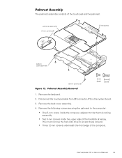
.... 4. Remove the following screws securing the palmrest to the computer: One 5-mm screw inside the upper edge of the hard-disk drive bay. (You must remove the hard-disk drive to the thermal cooling assembly. Dell Latitude CPi A Service Manual 19 Two 5-mm screws inside the computer, adjacent to access these screws.) Three 12-mm screws underneath...
.... 4. Remove the following screws securing the palmrest to the computer: One 5-mm screw inside the upper edge of the hard-disk drive bay. (You must remove the hard-disk drive to the thermal cooling assembly. Dell Latitude CPi A Service Manual 19 Two 5-mm screws inside the computer, adjacent to access these screws.) Three 12-mm screws underneath...

User Manual
Page 36
... remove the main battery or hard-disk drive prior to this by temporarily installing a device in the modular bay. (You can check this procedure. 1. Remove the device from the center of the modular bay with devices installed in the modular bay prior to reinstalling the palmrest assembly.) 30 Dell Latitude CPi A Service Manual Push the...
... remove the main battery or hard-disk drive prior to this by temporarily installing a device in the modular bay. (You can check this procedure. 1. Remove the device from the center of the modular bay with devices installed in the modular bay prior to reinstalling the palmrest assembly.) 30 Dell Latitude CPi A Service Manual Push the...

User Manual
Page 47
Tear the reserve battery free from connector JRBAT1 on the hard-disk drive bay so that there is minimal slack in the cable. NOTE: When you replace the reserve battery, first connect the reserve battery cable to the ... bottom case bracket. Remove the back cover assembly. 2. Remove the reserve battery from the system board assembly. Remove the palmrest assembly. 4. b. Remove the keyboard assembly. 3. Dell Latitude CPi A Service Manual 41 reserve battery reserve battery cable connector (JBAT1) To remove the reserve battery, perform the following steps: 1.
Tear the reserve battery free from connector JRBAT1 on the hard-disk drive bay so that there is minimal slack in the cable. NOTE: When you replace the reserve battery, first connect the reserve battery cable to the ... bottom case bracket. Remove the back cover assembly. 2. Remove the reserve battery from the system board assembly. Remove the palmrest assembly. 4. b. Remove the keyboard assembly. 3. Dell Latitude CPi A Service Manual 41 reserve battery reserve battery cable connector (JBAT1) To remove the reserve battery, perform the following steps: 1.
User Manual
Page 49
audio board removal, 31 audio shield removal, 30 back cover assembly removal, 18 battery (in modular bay) removal, 30 bottom case assembly components, 28 illustrated, 29 bottom case bracket removal, 32 CD-ROM drive removal, 30 diskette drive removal, 30 display assembly bezel, removal, 23 removal, 21 top cover, removal, 28 ESD, 2 exhaust fan removal, 39 field-replaceable parts and assemblies illustrated, 12 list of, 5 hard-disk drive assembly removal, 13 I/R board removal, 40 keyboard assembly removal, 16 Index 1
audio board removal, 31 audio shield removal, 30 back cover assembly removal, 18 battery (in modular bay) removal, 30 bottom case assembly components, 28 illustrated, 29 bottom case bracket removal, 32 CD-ROM drive removal, 30 diskette drive removal, 30 display assembly bezel, removal, 23 removal, 21 top cover, removal, 28 ESD, 2 exhaust fan removal, 39 field-replaceable parts and assemblies illustrated, 12 list of, 5 hard-disk drive assembly removal, 13 I/R board removal, 40 keyboard assembly removal, 16 Index 1


