User Manual
Page 3
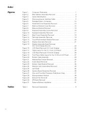
... 5 Removing Field-Replaceable Parts and Assemblies 12 Hard-Disk Drive Assembly 13 Memory Module Cover 14 Memory Modules 15 Keyboard Assembly 16 Back Cover Assembly 18 Palmrest Assembly 19 Touch-Pad Interface Module 20 Power Button 21 Display Assembly 21 Display Assembly Bezel 23 Display Assembly Latch 23 LCD Panel 24 12.1-Inch LCD Displays 24 13.3-Inch LCD Displays 26 LCD Display Hinge 28 Display-Assembly Top Cover 28 Bottom Case Assembly 28 Modular Bay Devices (Diskette Drive, CD-ROM Drive, Battery, or Travel Module 30 Audio...
... 5 Removing Field-Replaceable Parts and Assemblies 12 Hard-Disk Drive Assembly 13 Memory Module Cover 14 Memory Modules 15 Keyboard Assembly 16 Back Cover Assembly 18 Palmrest Assembly 19 Touch-Pad Interface Module 20 Power Button 21 Display Assembly 21 Display Assembly Bezel 23 Display Assembly Latch 23 LCD Panel 24 12.1-Inch LCD Displays 24 13.3-Inch LCD Displays 26 LCD Display Hinge 28 Display-Assembly Top Cover 28 Bottom Case Assembly 28 Modular Bay Devices (Diskette Drive, CD-ROM Drive, Battery, or Travel Module 30 Audio...
User Manual
Page 4
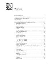
...1 Main Battery Assembly Removal 3 Screw Identification 3 Disconnecting an Interface Cable 4 Exploded View-Computer 12 Hard-Disk Drive Assembly Removal 13 Memory Module Cover Removal 14 Memory Module Removal 15 Keyboard Assembly Screw Removal 16 Keyboard Assembly Removal 17 Back Cover Assembly Removal 18 Palmrest Assembly Removal 19 Touch-Pad Interface Module Removal 20 Display Assembly Removal 21 Display Assembly Bezel Removal (12.1-Inch Display Shown 23 LCD Panel Removal (12.1-Inch Display 24 Cable Layout for the 12.1-Inch LCD Panel 25 LCD Panel Removal (13.3-Inch Display 26...
...1 Main Battery Assembly Removal 3 Screw Identification 3 Disconnecting an Interface Cable 4 Exploded View-Computer 12 Hard-Disk Drive Assembly Removal 13 Memory Module Cover Removal 14 Memory Module Removal 15 Keyboard Assembly Screw Removal 16 Keyboard Assembly Removal 17 Back Cover Assembly Removal 18 Palmrest Assembly Removal 19 Touch-Pad Interface Module Removal 20 Display Assembly Removal 21 Display Assembly Bezel Removal (12.1-Inch Display Shown 23 LCD Panel Removal (12.1-Inch Display 24 Cable Layout for the 12.1-Inch LCD Panel 25 LCD Panel Removal (13.3-Inch Display 26...
User Manual
Page 7
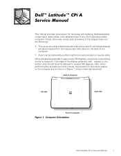
... noted, each procedure in your Dell Latitude portable computer. When the display assembly is open nearly 180 degrees, use a book or something similar to the bottom case should never be replaced by performing the removal procedure in Figure 1 unless otherwise specified. This manual provides instructions for removing and replacing field-replaceable components, assemblies, and subassemblies in this manual, the locations or directions relative to the...
... noted, each procedure in your Dell Latitude portable computer. When the display assembly is open nearly 180 degrees, use a book or something similar to the bottom case should never be replaced by performing the removal procedure in Figure 1 unless otherwise specified. This manual provides instructions for removing and replacing field-replaceable components, assemblies, and subassemblies in this manual, the locations or directions relative to the...
User Manual
Page 8
.... 4. Remove any work on the computer, perform the following steps: 1. Remove the main battery assembly from the computer. 7. Remove the power cord. 6. NOTE: Make sure the computer is docked in progress and close all other external cables from the battery bay. Slide the battery bay latch away from the center of the battery bay (see Figure 2). 2 Dell Latitude CPi A Service Manual Save any installed PC Cards. 8. Then slide the battery...
.... 4. Remove any work on the computer, perform the following steps: 1. Remove the main battery assembly from the computer. 7. Remove the power cord. 6. NOTE: Make sure the computer is docked in progress and close all other external cables from the battery bay. Slide the battery bay latch away from the center of the battery bay (see Figure 2). 2 Dell Latitude CPi A Service Manual Save any installed PC Cards. 8. Then slide the battery...
User Manual
Page 10
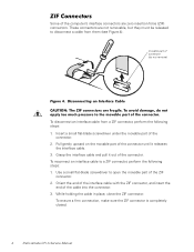
... until it out of the connector. To ensure a firm connection, make sure the ZIF connector is completely closed. 4 Dell Latitude CPi A Service Manual Use a small flat-blade screwdriver to open the movable part of the connector. 2. While holding the cable in place, close the ZIF connector. Some of the computer's interface connectors are not removable, but they must be released to disconnect...
... until it out of the connector. To ensure a firm connection, make sure the ZIF connector is completely closed. 4 Dell Latitude CPi A Service Manual Use a small flat-blade screwdriver to open the movable part of the connector. 2. While holding the cable in place, close the ZIF connector. Some of the computer's interface connectors are not removable, but they must be released to disconnect...
User Manual
Page 11
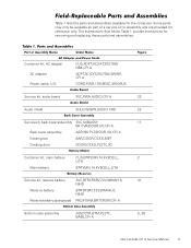
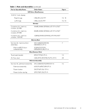
...,14.4V,8CELL,LITH Service kit, reserve battery Reserve battery Reserve battery sponge pad SVC,BTRY,RSRV,7.2V,30MAH,6, NIHD BTRY,RSRV,7.2V,30MAH,6, NIHD PAD,FOAM,BRTY,RSRV,CPi A Bottom case assembly ASSY,CVR,BTM,PLSTC, BASE,CPi A 22 22 11 2 31 5, 26 Dell Latitude CPi A Service Manual 5 Customer kit, AC adapter AC adapter Power cable, U.S. Some parts may only be available as part of a service kit or assembly...
...,14.4V,8CELL,LITH Service kit, reserve battery Reserve battery Reserve battery sponge pad SVC,BTRY,RSRV,7.2V,30MAH,6, NIHD BTRY,RSRV,7.2V,30MAH,6, NIHD PAD,FOAM,BRTY,RSRV,CPi A Bottom case assembly ASSY,CVR,BTM,PLSTC, BASE,CPi A 22 22 11 2 31 5, 26 Dell Latitude CPi A Service Manual 5 Customer kit, AC adapter AC adapter Power cable, U.S. Some parts may only be available as part of a service kit or assembly...
User Manual
Page 14
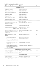
...,OVAL,ADH CVR,SCR,TOP,OVAL,SM,ADH,12.1 16, 17 15 13.3-inch LCD/Cable service kit, SVC,LCD/CBL/INV,TFT,zzz,13.3", including LCD, brackets, cable, CPi A* inverter, and bezel 18, 19 Latch service kit SVC,LATCH,DIS,BZL,CPi A * Substitute the drive capacity for xxxxx, the drive height for yy, and the manufacturer for zzz. 14, 15 8 Dell Latitude CPi A Service Manual
...,OVAL,ADH CVR,SCR,TOP,OVAL,SM,ADH,12.1 16, 17 15 13.3-inch LCD/Cable service kit, SVC,LCD/CBL/INV,TFT,zzz,13.3", including LCD, brackets, cable, CPi A* inverter, and bezel 18, 19 Latch service kit SVC,LATCH,DIS,BZL,CPi A * Substitute the drive capacity for xxxxx, the drive height for yy, and the manufacturer for zzz. 14, 15 8 Dell Latitude CPi A Service Manual
User Manual
Page 15
... CPi A,FACT 128MB,DIMM,SDRAM,LAT CPi A,FACT Service kit, memory door SVC,SUBASSY,DOOR, 7 assembly MEM/BIOS,CPi A Memory/BIOS door subassembly SUBASSY,DOOR, MEM/BIOS,NB,CPi A Touch-pad bracket Air flow duct BRCKT,TPAD,CPi A 13 GDE,INTK,AIR,FAN,PLSTC,CPi A 26 Service kit, palmrest assembly SVC,SUBASSY,PLMRST,CPi A 12 Palmrest assembly ASSY,PLMRST,GRY,CPi A Power button SWT,PWR SW, CPi A Power button spring SPR,PWR SW,CPi A Dell Latitude CPi A Service Manual...
... CPi A,FACT 128MB,DIMM,SDRAM,LAT CPi A,FACT Service kit, memory door SVC,SUBASSY,DOOR, 7 assembly MEM/BIOS,CPi A Memory/BIOS door subassembly SUBASSY,DOOR, MEM/BIOS,NB,CPi A Touch-pad bracket Air flow duct BRCKT,TPAD,CPi A 13 GDE,INTK,AIR,FAN,PLSTC,CPi A 26 Service kit, palmrest assembly SVC,SUBASSY,PLMRST,CPi A 12 Palmrest assembly ASSY,PLMRST,GRY,CPi A Power button SWT,PWR SW, CPi A Power button spring SPR,PWR SW,CPi A Dell Latitude CPi A Service Manual...
User Manual
Page 16
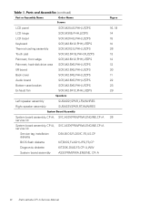
LCD panel LCD hinge LCD bezel Keyboard Thermal cooling assembly Touch pad Palmrest, front edge Palmrest, hard-disk drive area I/R board Back cover Audio board Bottom-case bracket Exhaust fan SCR,M2X4.5,PHH,LP,ZPS ...board assembly, CPi A, SVC,ASSY,PRM/PWA,ENGINE,CPi A 26 service kit System board assembly, CPi A, SVC,ASSY,PRM/PWA,ENGINE,CPi A service kit Service tag installation diskette DSK,BIOS,FLDSVC,F3,US,CP BIOS flash diskette KIT,BIOS,FLASH,UPG,F3,CP Diagnostic diskette KIT,DSK,DIAG,F3,CPi A,WW System board assembly ASSY,PRM/PWA,ENGINE, CPi A 10 Dell Latitude CPi A Service Manual
LCD panel LCD hinge LCD bezel Keyboard Thermal cooling assembly Touch pad Palmrest, front edge Palmrest, hard-disk drive area I/R board Back cover Audio board Bottom-case bracket Exhaust fan SCR,M2X4.5,PHH,LP,ZPS ...board assembly, CPi A, SVC,ASSY,PRM/PWA,ENGINE,CPi A 26 service kit System board assembly, CPi A, SVC,ASSY,PRM/PWA,ENGINE,CPi A service kit Service tag installation diskette DSK,BIOS,FLDSVC,F3,US,CP BIOS flash diskette KIT,BIOS,FLASH,UPG,F3,CP Diagnostic diskette KIT,DSK,DIAG,F3,CPi A,WW System board assembly ASSY,PRM/PWA,ENGINE, CPi A 10 Dell Latitude CPi A Service Manual
User Manual
Page 17
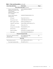
... battery Foam pad ASSY,PRM/PWA,ENGINE, CPi A SUBASSY,PWA/ENGINE,CPi A PWA,FAST IR,CPi A GRMT,RBR,BOOT,MCPHN PWA,PLN,0M,NB,CPi A PWA,DTRBD,VID/PCMCIA,CPi A PWA,LED,CPi A FAN,25X25X10,CPi A MCPHN,CPi A BTRY,RSRV,7.2,30MAH,6,NIHD PAD,FOAM,BTRY,RSRV,CPi A Service kit, thermal cooling SVC,SUBASSY,HTSNK, 26 subassembly CPU,HYB,CPi A Touch-pad service kit SVC,TPAD,SQ,INTFC,CPi A 13 Touch-pad subassembly TPA,INTFC,CPi A Dell Latitude CPi A Service Manual...
... battery Foam pad ASSY,PRM/PWA,ENGINE, CPi A SUBASSY,PWA/ENGINE,CPi A PWA,FAST IR,CPi A GRMT,RBR,BOOT,MCPHN PWA,PLN,0M,NB,CPi A PWA,DTRBD,VID/PCMCIA,CPi A PWA,LED,CPi A FAN,25X25X10,CPi A MCPHN,CPi A BTRY,RSRV,7.2,30MAH,6,NIHD PAD,FOAM,BTRY,RSRV,CPi A Service kit, thermal cooling SVC,SUBASSY,HTSNK, 26 subassembly CPU,HYB,CPi A Touch-pad service kit SVC,TPAD,SQ,INTFC,CPi A 13 Touch-pad subassembly TPA,INTFC,CPi A Dell Latitude CPi A Service Manual...
User Manual
Page 18
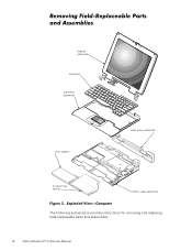
display assembly keyboard palmrest assembly main battery back cover assembly modular bay device bottom case assembly The following subsections provide instructions for removing and replacing field-replaceable parts and assemblies. 12 Dell Latitude CPi A Service Manual
display assembly keyboard palmrest assembly main battery back cover assembly modular bay device bottom case assembly The following subsections provide instructions for removing and replacing field-replaceable parts and assemblies. 12 Dell Latitude CPi A Service Manual
User Manual
Page 21
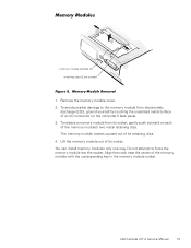
... the memory module from its socket, gently push outward on the computer's back panel. 3. The memory module rotates upward out of the memory module with the corresponding key in the memory module socket. Align the notch near the center of its socket. To avoid possible damage to force the memory module into the socket. You can install memory modules only one way. Dell Latitude CPi A Service Manual 15 Remove the memory module cover. 2. memory module sockets...
... the memory module from its socket, gently push outward on the computer's back panel. 3. The memory module rotates upward out of the memory module with the corresponding key in the memory module socket. Align the notch near the center of its socket. To avoid possible damage to force the memory module into the socket. You can install memory modules only one way. Dell Latitude CPi A Service Manual 15 Remove the memory module cover. 2. memory module sockets...
User Manual
Page 22
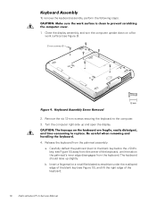
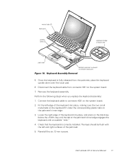
Release the keyboard from the keyboard. Remove the six 12-mm screws securing the keyboard to the blank key below the key; b. see Figure 9). 12-mm screws (6) 2. The keyboard should raise up and open the display. 4. Close the display assembly, and turn the computer upside down on a flat work surface (see Figure 10) away from the center of the keyboard. 16 Dell Latitude CPi A Service Manual Carefully deflect the...
Release the keyboard from the keyboard. Remove the six 12-mm screws securing the keyboard to the blank key below the key; b. see Figure 9). 12-mm screws (6) 2. The keyboard should raise up and open the display. 4. Close the display assembly, and turn the computer upside down on a flat work surface (see Figure 10) away from the center of the keyboard. 16 Dell Latitude CPi A Service Manual Carefully deflect the...
User Manual
Page 23
... to connector KB1 on the system board. 2. Disconnect the keyboard cable from the palmrest, place the keyboard upside down over the touch pad. 6. Fit the left and right surfaces of the palmrest. 5. Reinstall the six 12-mm screws. Once the keyboard is correctly installed. Remove the keyboard assembly. The keys should be flush with an audible "click." 4. Dell Latitude CPi A Service Manual 17 Connect the keyboard cable to release...
... to connector KB1 on the system board. 2. Disconnect the keyboard cable from the palmrest, place the keyboard upside down over the touch pad. 6. Fit the left and right surfaces of the palmrest. 5. Reinstall the six 12-mm screws. Once the keyboard is correctly installed. Remove the keyboard assembly. The keys should be flush with an audible "click." 4. Dell Latitude CPi A Service Manual 17 Connect the keyboard cable to release...
User Manual
Page 26
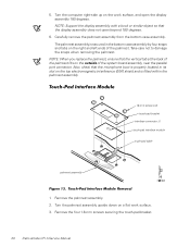
..., check that the microphone boot is fitted within the palmrest assembly. 1.8-mm screws (4) touch-pad bracket interface connector J1 touch-pad interface module touch-pad cable palmrest assembly 1. Remove the four 1.8-mm screws securing the touch-pad bracket. 20 Dell Latitude CPi A Service Manual NOTE: Support the display assembly with a book or similar object so that the vertical tab at the back of the palmrest fits on the work surface. 3. Take care...
..., check that the microphone boot is fitted within the palmrest assembly. 1.8-mm screws (4) touch-pad bracket interface connector J1 touch-pad interface module touch-pad cable palmrest assembly 1. Remove the four 1.8-mm screws securing the touch-pad bracket. 20 Dell Latitude CPi A Service Manual NOTE: Support the display assembly with a book or similar object so that the vertical tab at the back of the palmrest fits on the work surface. 3. Take care...
User Manual
Page 30
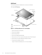
The following subsections describe how to remove an LCD panel. Remove the two screws holding the interface connector. 7. LCD panel interface connector 4.5-mm screws (2) LCD panel power cable display-assembly top cover LCD inverter board 1. Remove the two 4.5-mm screws at the right corners of the LCD panel. 6. Disconnect the interface connector. Remove the back cover assembly. 2. Remove the palmrest. 4. Remove the display assembly bezel. 5. Figure 17 shows the cable layout for a 12.1-inch LCD panel. 24 Dell Latitude CPi A Service Manual Remove the keyboard. 3.
The following subsections describe how to remove an LCD panel. Remove the two screws holding the interface connector. 7. LCD panel interface connector 4.5-mm screws (2) LCD panel power cable display-assembly top cover LCD inverter board 1. Remove the two 4.5-mm screws at the right corners of the LCD panel. 6. Disconnect the interface connector. Remove the back cover assembly. 2. Remove the palmrest. 4. Remove the display assembly bezel. 5. Figure 17 shows the cable layout for a 12.1-inch LCD panel. 24 Dell Latitude CPi A Service Manual Remove the keyboard. 3.
User Manual
Page 32
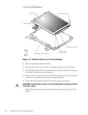
... connector tape from the interface cable at the right corners of the LCD panel, slide the LCD panel to the right, and then pivot the panel up. 4. Figure 19 shows the two-piece (A and B) cable layout for a 13.3-inch LCD panel. 26 Dell Latitude CPi A Service Manual Disconnect the interface cable at the center-junction connector. Remove the display assembly bezel. 2. LCD panel interface cable 4.5-mm screws (2) display-assembly top cover LCD inverter board LCD panel power cable 1.
... connector tape from the interface cable at the right corners of the LCD panel, slide the LCD panel to the right, and then pivot the panel up. 4. Figure 19 shows the two-piece (A and B) cable layout for a 13.3-inch LCD panel. 26 Dell Latitude CPi A Service Manual Disconnect the interface cable at the center-junction connector. Remove the display assembly bezel. 2. LCD panel interface cable 4.5-mm screws (2) display-assembly top cover LCD inverter board LCD panel power cable 1.
User Manual
Page 33
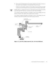
... LCD A cable interface connector Dell Latitude CPi A Service Manual 27 Disconnect the display-assembly interface cable from the ZIF connector on the 13.3-inch display, use two bends to route the new cable to the inverter board connector. LCD B cable (stays with the LCD display. Do not pull on the 12.1-inch display, use one that is located on the right side of the LCD panel. 6. If you need to replace the bottom LCD cable on the LCD panel...
... LCD A cable interface connector Dell Latitude CPi A Service Manual 27 Disconnect the display-assembly interface cable from the ZIF connector on the 13.3-inch display, use two bends to route the new cable to the inverter board connector. LCD B cable (stays with the LCD display. Do not pull on the 12.1-inch display, use one that is located on the right side of the LCD panel. 6. If you need to replace the bottom LCD cable on the LCD panel...
User Manual
Page 44
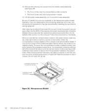
... 38 Dell Latitude CPi A Service Manual processor hold -down evenly at the holes on the thermal pad before installing the new thermal cooling assembly. After replacing the system board assembly, be at the same height. To ensure the microprocessor module is seated, all four corners of the bottom case assembly. Install the three screws to secure the microprocessor module to enter the system's service tag number...
... 38 Dell Latitude CPi A Service Manual processor hold -down evenly at the holes on the thermal pad before installing the new thermal cooling assembly. After replacing the system board assembly, be at the same height. To ensure the microprocessor module is seated, all four corners of the bottom case assembly. Install the three screws to secure the microprocessor module to enter the system's service tag number...

User Manual
Page 50
... display hinge removal, 28 LCD panel removal, 24, 26 reserve battery removal, 41 main battery assembly removal, 2 memory module removal, 15 memory module cover removal, 14 modular bay devices removal, 30 module latch assemblies removal, 33 module latch assemblies removal, 33 screw identification and tightening, 3 sockets memory module, 15 speakers removal, 34 system board assembly removal, 35 tools, 2 touch-pad interface module removal, 20 travel module removal, 30 palmrest assembly removal, 19 power button removal, 21 preparing to work, 2 ZIF connectors, 4 2 Dell Latitude CPi A Service...
... display hinge removal, 28 LCD panel removal, 24, 26 reserve battery removal, 41 main battery assembly removal, 2 memory module removal, 15 memory module cover removal, 14 modular bay devices removal, 30 module latch assemblies removal, 33 module latch assemblies removal, 33 screw identification and tightening, 3 sockets memory module, 15 speakers removal, 34 system board assembly removal, 35 tools, 2 touch-pad interface module removal, 20 travel module removal, 30 palmrest assembly removal, 19 power button removal, 21 preparing to work, 2 ZIF connectors, 4 2 Dell Latitude CPi A Service...


