User Manual
Page 7
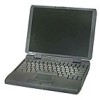
..., and subassemblies in this manual, the locations or directions relative to the computer are disconnected from the input/output (I/O) panel on the back of computer Dell Latitude CPi A Service Manual 1 When the display assembly is open nearly 180 degrees, use a book or something similar to exceed 180 degrees. Also, when performing the procedures... turned off, and the peripherals are as shown in reverse order. A part can be allowed to support it. Unless otherwise noted, each procedure in your Dell Latitude portable computer.
..., and subassemblies in this manual, the locations or directions relative to the computer are disconnected from the input/output (I/O) panel on the back of computer Dell Latitude CPi A Service Manual 1 When the display assembly is open nearly 180 degrees, use a book or something similar to exceed 180 degrees. Also, when performing the procedures... turned off, and the peripherals are as shown in reverse order. A part can be allowed to support it. Unless otherwise noted, each procedure in your Dell Latitude portable computer.
User Manual
Page 8
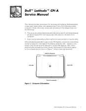
Slide the battery bay latch away from the center of the battery bay (see Figure 2). 2 Dell Latitude CPi A Service Manual If you start to reduce the potential for 4 seconds. 3. Remove the power cord. 6. Then slide the battery out of the computer. If the ...
Slide the battery bay latch away from the center of the battery bay (see Figure 2). 2 Dell Latitude CPi A Service Manual If you start to reduce the potential for 4 seconds. 3. Remove the power cord. 6. Then slide the battery out of the computer. If the ...
User Manual
Page 9
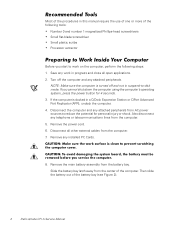
Dell Latitude CPi A Service Manual 3 A graphic for correct length. 9. Examples are shown in the illustration. The illustrations in the following removal procedures provide the correct screw length as part of the I /O panel to check for that might harm components. While you work, periodically touch the I /O panel on the back of the computer. Ground yourself by touching the unpainted metal surface of the screw's label. Match the actual screw to the graphic in the illustration to dissipate any static electricity that length screw is also included in Figure 3.
Dell Latitude CPi A Service Manual 3 A graphic for correct length. 9. Examples are shown in the illustration. The illustrations in the following removal procedures provide the correct screw length as part of the I /O panel to check for that might harm components. While you work, periodically touch the I /O panel on the back of the computer. Ground yourself by touching the unpainted metal surface of the screw's label. Match the actual screw to the graphic in the illustration to dissipate any static electricity that length screw is also included in Figure 3.
User Manual
Page 10
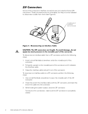
... connector. 3. Use a small flat-blade screwdriver to a ZIF connector, perform the following steps: 1. To ensure a firm connection, make sure the ZIF connector is completely closed. 4 Dell Latitude CPi A Service Manual These connectors are zero insertion force (ZIF) connectors.
... connector. 3. Use a small flat-blade screwdriver to a ZIF connector, perform the following steps: 1. To ensure a firm connection, make sure the ZIF connector is completely closed. 4 Dell Latitude CPi A Service Manual These connectors are zero insertion force (ZIF) connectors.
User Manual
Page 11
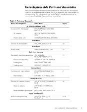
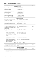
...,6F,AC,3W\3P,US Service kit, audio board SVC,PWA,AUDIO,CPi A Audio shield SHLD,W/SPR,AUDIO CRD Service kit, back cover assembly SVC,SUBASSY, BK CVR/DOOR,I/O,CPi A Back cover assembly ASSY,BK PLT/DOOR,I/O,CPi A Docking bar BAR,DOOR,DCKG,MET Docking door DOOR,DCKG,PLSTC,I/O...battery sponge pad SVC,BTRY,RSRV,7.2V,30MAH,6, NIHD BTRY,RSRV,7.2V,30MAH,6, NIHD PAD,FOAM,BRTY,RSRV,CPi A Bottom case assembly ASSY,CVR,BTM,PLSTC, BASE,CPi A 22 22 11 2 31 5, 26 Dell Latitude CPi A Service Manual 5 Table 1 lists the parts and assemblies available for removing and replacing these parts and ...
...,6F,AC,3W\3P,US Service kit, audio board SVC,PWA,AUDIO,CPi A Audio shield SHLD,W/SPR,AUDIO CRD Service kit, back cover assembly SVC,SUBASSY, BK CVR/DOOR,I/O,CPi A Back cover assembly ASSY,BK PLT/DOOR,I/O,CPi A Docking bar BAR,DOOR,DCKG,MET Docking door DOOR,DCKG,PLSTC,I/O...battery sponge pad SVC,BTRY,RSRV,7.2V,30MAH,6, NIHD BTRY,RSRV,7.2V,30MAH,6, NIHD PAD,FOAM,BRTY,RSRV,CPi A Bottom case assembly ASSY,CVR,BTM,PLSTC, BASE,CPi A 22 22 11 2 31 5, 26 Dell Latitude CPi A Service Manual 5 Table 1 lists the parts and assemblies available for removing and replacing these parts and ...
User Manual
Page 12
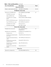
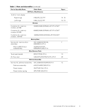
... drive label SVC,SUBASSY,CD,24X,NBK BZL,CD CD,680M,INT,NBK PWA,CD/FDD INTERCONN,SE CVR,BTM,PLSTC,CD,CPi A CVR,TOP,PLSTC,CD,CPi A SHLD,CD,CPi A LBL,REG,CD,24X Diskette drive service kit Diskette drive subassembly Diskette drive Diskette drive assembly bottom cover Diskette drive assembly top... assembly shield SVC,SUBASSY,FD,F3, INT/EXT,CPi A SUBASSY,FD,F3,INT/EXT,CPi A FD,F3,CPi A CVR,BTM,PLSTC,FD,F3,CPi A CVR,TOP,PLSTC,FD,F3,CPi A PWA,INTFC,FD,F3,CPi A CBL,FPC,FD,F3,CPi A SHLD,FD,F3,CPi A Service kit, exhaust fan SVC,FAN,25X25X10,CPi A 20, 23 21 21 29 6 Dell Latitude CPi A Service Manual
... drive label SVC,SUBASSY,CD,24X,NBK BZL,CD CD,680M,INT,NBK PWA,CD/FDD INTERCONN,SE CVR,BTM,PLSTC,CD,CPi A CVR,TOP,PLSTC,CD,CPi A SHLD,CD,CPi A LBL,REG,CD,24X Diskette drive service kit Diskette drive subassembly Diskette drive Diskette drive assembly bottom cover Diskette drive assembly top... assembly shield SVC,SUBASSY,FD,F3, INT/EXT,CPi A SUBASSY,FD,F3,INT/EXT,CPi A FD,F3,CPi A CVR,BTM,PLSTC,FD,F3,CPi A CVR,TOP,PLSTC,FD,F3,CPi A PWA,INTFC,FD,F3,CPi A CBL,FPC,FD,F3,CPi A SHLD,FD,F3,CPi A Service kit, exhaust fan SVC,FAN,25X25X10,CPi A 20, 23 21 21 29 6 Dell Latitude CPi A Service Manual
User Manual
Page 13
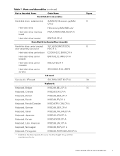
...,88,GER,CPi A Keyboard, Italian KYBD,88,ITALIAN,CPi A Keyboard, Japanese KYBD,90,JPN,CPi A Keyboard, Korean KYBD,87,KOR,CPi A Keyboard, Latin American KYBD,88,LAC,CPi A Keyboard, Norwegian KYBD,88,NOR,CPi A Keyboard, Portuguese KYBD,88,PORTUGEUSE,CPi A * Substitute the drive capacity for xxxxx, the drive height for yy, and the manufacturer for zzz. Dell Latitude CPi A Service...
...,88,GER,CPi A Keyboard, Italian KYBD,88,ITALIAN,CPi A Keyboard, Japanese KYBD,90,JPN,CPi A Keyboard, Korean KYBD,87,KOR,CPi A Keyboard, Latin American KYBD,88,LAC,CPi A Keyboard, Norwegian KYBD,88,NOR,CPi A Keyboard, Portuguese KYBD,88,PORTUGEUSE,CPi A * Substitute the drive capacity for xxxxx, the drive height for yy, and the manufacturer for zzz. Dell Latitude CPi A Service...
User Manual
Page 14
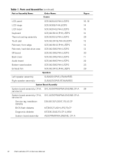
.../Finnish Keyboard, Swiss Keyboard, Thai Keyboard, English (U.K.) Keyboard, English (U.S.) KYBD,87,RUS,CPi A KYBD,88,SPN,CPi A KYBD,88,SWE,CPi A KYBD,88,SWI,CPi A KYBD,87,THAI,CPi A KYBD,88,UK,CPi A KYBD,87,DOM,CPi A Display top-cover service kit, 13.3/12.1-inch display Display top cover Display top-cover... kit, SVC,LCD/CBL/INV,TFT,zzz,13.3", including LCD, brackets, cable, CPi A* inverter, and bezel 18, 19 Latch service kit SVC,LATCH,DIS,BZL,CPi A * Substitute the drive capacity for xxxxx, the drive height for yy, and the manufacturer for zzz. 14, 15 8 Dell Latitude CPi A Service Manual
.../Finnish Keyboard, Swiss Keyboard, Thai Keyboard, English (U.K.) Keyboard, English (U.S.) KYBD,87,RUS,CPi A KYBD,88,SPN,CPi A KYBD,88,SWE,CPi A KYBD,88,SWI,CPi A KYBD,87,THAI,CPi A KYBD,88,UK,CPi A KYBD,87,DOM,CPi A Display top-cover service kit, 13.3/12.1-inch display Display top cover Display top-cover... kit, SVC,LCD/CBL/INV,TFT,zzz,13.3", including LCD, brackets, cable, CPi A* inverter, and bezel 18, 19 Latch service kit SVC,LATCH,DIS,BZL,CPi A * Substitute the drive capacity for xxxxx, the drive height for yy, and the manufacturer for zzz. 14, 15 8 Dell Latitude CPi A Service Manual
User Manual
Page 15
.../BIOS,CPi A Memory/BIOS door subassembly SUBASSY,DOOR, MEM/BIOS,NB,CPi A Touch-pad bracket Air flow duct BRCKT,TPAD,CPi A 13 GDE,INTK,AIR,FAN,PLSTC,CPi A 26 Service kit, palmrest assembly SVC,SUBASSY,PLMRST,CPi A 12 Palmrest assembly ASSY,PLMRST,GRY,CPi A Power button SWT,PWR SW, CPi A Power button spring SPR,PWR SW,CPi A Dell Latitude CPi A Service...
.../BIOS,CPi A Memory/BIOS door subassembly SUBASSY,DOOR, MEM/BIOS,NB,CPi A Touch-pad bracket Air flow duct BRCKT,TPAD,CPi A 13 GDE,INTK,AIR,FAN,PLSTC,CPi A 26 Service kit, palmrest assembly SVC,SUBASSY,PLMRST,CPi A 12 Palmrest assembly ASSY,PLMRST,GRY,CPi A Power button SWT,PWR SW, CPi A Power button spring SPR,PWR SW,CPi A Dell Latitude CPi A Service...
User Manual
Page 16
...speaker assembly SUBASSY,SPKR,LF,W/WIRES SUBASSY,SPKR,RT,W/WIRES System board assembly, CPi A, SVC,ASSY,PRM/PWA,ENGINE,CPi A 26 service kit System board assembly, CPi A, SVC,ASSY,PRM/PWA,ENGINE,CPi A service kit Service tag installation diskette DSK,BIOS,FLDSVC,F3,US,CP ...BIOS flash diskette KIT,BIOS,FLASH,UPG,F3,CP Diagnostic diskette KIT,DSK,DIAG,F3,CPi A,WW System board assembly ASSY,PRM/PWA,ENGINE, CPi A 10 Dell Latitude CPi...
...speaker assembly SUBASSY,SPKR,LF,W/WIRES SUBASSY,SPKR,RT,W/WIRES System board assembly, CPi A, SVC,ASSY,PRM/PWA,ENGINE,CPi A 26 service kit System board assembly, CPi A, SVC,ASSY,PRM/PWA,ENGINE,CPi A service kit Service tag installation diskette DSK,BIOS,FLDSVC,F3,US,CP ...BIOS flash diskette KIT,BIOS,FLASH,UPG,F3,CP Diagnostic diskette KIT,DSK,DIAG,F3,CPi A,WW System board assembly ASSY,PRM/PWA,ENGINE, CPi A 10 Dell Latitude CPi...
User Manual
Page 17
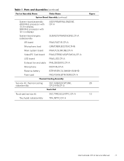
... pad ASSY,PRM/PWA,ENGINE, CPi A SUBASSY,PWA/ENGINE,CPi A PWA,FAST IR,CPi A GRMT,RBR,BOOT,MCPHN PWA,PLN,0M,NB,CPi A PWA,DTRBD,VID/PCMCIA,CPi A PWA,LED,CPi A FAN,25X25X10,CPi A MCPHN,CPi A BTRY,RSRV,7.2,30MAH,6,NIHD PAD,FOAM,BTRY,RSRV,CPi A Service kit, thermal cooling SVC...,SUBASSY,HTSNK, 26 subassembly CPU,HYB,CPi A Touch-pad service kit SVC,TPAD,SQ,INTFC,CPi A 13 Touch-pad subassembly TPA,INTFC,CPi A Dell Latitude CPi...
... pad ASSY,PRM/PWA,ENGINE, CPi A SUBASSY,PWA/ENGINE,CPi A PWA,FAST IR,CPi A GRMT,RBR,BOOT,MCPHN PWA,PLN,0M,NB,CPi A PWA,DTRBD,VID/PCMCIA,CPi A PWA,LED,CPi A FAN,25X25X10,CPi A MCPHN,CPi A BTRY,RSRV,7.2,30MAH,6,NIHD PAD,FOAM,BTRY,RSRV,CPi A Service kit, thermal cooling SVC...,SUBASSY,HTSNK, 26 subassembly CPU,HYB,CPi A Touch-pad service kit SVC,TPAD,SQ,INTFC,CPi A 13 Touch-pad subassembly TPA,INTFC,CPi A Dell Latitude CPi...
User Manual
Page 18
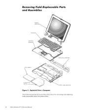
display assembly keyboard palmrest assembly main battery back cover assembly modular bay device bottom case assembly The following subsections provide instructions for removing and replacing field-replaceable parts and assemblies. 12 Dell Latitude CPi A Service Manual
display assembly keyboard palmrest assembly main battery back cover assembly modular bay device bottom case assembly The following subsections provide instructions for removing and replacing field-replaceable parts and assemblies. 12 Dell Latitude CPi A Service Manual
User Manual
Page 19
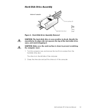
Grasp the drive door and pull the drive out of the computer. 2. Dell Latitude CPi A Service Manual 13 Turn the computer over, and remove the two 5-mm screws from the hard-disk drive door. The drive is on the left side of the computer. 5-mm screws (2) hard-disk drive door 1.
Grasp the drive door and pull the drive out of the computer. 2. Dell Latitude CPi A Service Manual 13 Turn the computer over, and remove the two 5-mm screws from the hard-disk drive door. The drive is on the left side of the computer. 5-mm screws (2) hard-disk drive door 1.
User Manual
Page 20
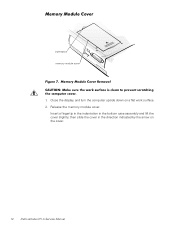
Insert a fingertip in the indentation in the direction indicated by the arrow on a flat work surface. 2. Close the display, and turn the computer upside down on the cover. 14 Dell Latitude CPi A Service Manual Release the memory module cover. indentation memory module cover 1. then slide the cover in the bottom case assembly and lift the cover slightly;
Insert a fingertip in the indentation in the direction indicated by the arrow on a flat work surface. 2. Close the display, and turn the computer upside down on the cover. 14 Dell Latitude CPi A Service Manual Release the memory module cover. indentation memory module cover 1. then slide the cover in the bottom case assembly and lift the cover slightly;
User Manual
Page 21
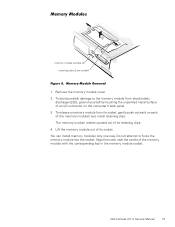
... socket) 1. You can install memory modules only one way. Remove the memory module cover. 2. Do not attempt to the memory module from its retaining clips. 4. Dell Latitude CPi A Service Manual 15 To release a memory module from electrostatic discharge (ESD), ground yourself by touching the unpainted metal surface of the memory module with the...
... socket) 1. You can install memory modules only one way. Remove the memory module cover. 2. Do not attempt to the memory module from its retaining clips. 4. Dell Latitude CPi A Service Manual 15 To release a memory module from electrostatic discharge (ESD), ground yourself by touching the unpainted metal surface of the memory module with the...
User Manual
Page 22
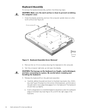
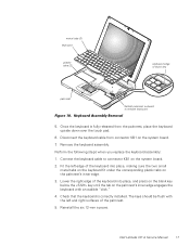
... key; To remove the keyboard assembly, perform the following steps. 1. Insert a fingernail or a small flat-bladed screwdriver under the scalloped edge of the keyboard. 16 Dell Latitude CPi A Service Manual Close the display assembly, and turn the computer upside down on the palmrest's inner edge disengages from the palmrest assembly: a.
... key; To remove the keyboard assembly, perform the following steps. 1. Insert a fingernail or a small flat-bladed screwdriver under the scalloped edge of the keyboard. 16 Dell Latitude CPi A Service Manual Close the display assembly, and turn the computer upside down on the palmrest's inner edge disengages from the palmrest assembly: a.
User Manual
Page 23
... small metal tabs on the keyboard fit under the corresponding plastic tabs on the system board. 2. The keys should be flush with an audible "click." 4. Dell Latitude CPi A Service Manual 17 metal tabs (2) keyboard plastic tabs (2) scalloped edge of blank key palmrest deflect palmrest outward to connector KB1 on the palmrest's inner edge...
... small metal tabs on the keyboard fit under the corresponding plastic tabs on the system board. 2. The keys should be flush with an audible "click." 4. Dell Latitude CPi A Service Manual 17 metal tabs (2) keyboard plastic tabs (2) scalloped edge of blank key palmrest deflect palmrest outward to connector KB1 on the palmrest's inner edge...
User Manual
Page 24
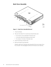
5-mm screws (12) 1. Close the docking connector door. 4. Remove the back cover assembly. Grasp the right end of the back cover 3. Remove the twelve 5-mm screws securing the back cover: Five screws on the underside of the back cover One screw behind the docking connector door Six screws on the face of the back cover assembly firmly, and unsnap it from the computer. Close the display. 2. Then disengage the left end of the back cover assembly. 18 Dell Latitude CPi A Service Manual
5-mm screws (12) 1. Close the docking connector door. 4. Remove the back cover assembly. Grasp the right end of the back cover 3. Remove the twelve 5-mm screws securing the back cover: Five screws on the underside of the back cover One screw behind the docking connector door Six screws on the face of the back cover assembly firmly, and unsnap it from the computer. Close the display. 2. Then disengage the left end of the back cover assembly. 18 Dell Latitude CPi A Service Manual
User Manual
Page 25
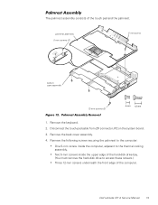
...: One 5-mm screw inside the upper edge of the hard-disk drive bay. (You must remove the hard-disk drive to the thermal cooling assembly. Dell Latitude CPi A Service Manual 19 Remove the back cover assembly. 4. Remove the keyboard. 2. The palmrest assembly consists of the computer.
...: One 5-mm screw inside the upper edge of the hard-disk drive bay. (You must remove the hard-disk drive to the thermal cooling assembly. Dell Latitude CPi A Service Manual 19 Remove the back cover assembly. 4. Remove the keyboard. 2. The palmrest assembly consists of the computer.
User Manual
Page 26
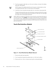
... ends of the palmrest fits on a flat work surface, and open beyond 180 degrees. 6. Remove the four 1.8-mm screws securing the touch-pad bracket. 20 Dell Latitude CPi A Service Manual Take care not to damage the snaps when removing the palmrest. Also, check that the vertical tab at the back of the palmrest...
... ends of the palmrest fits on a flat work surface, and open beyond 180 degrees. 6. Remove the four 1.8-mm screws securing the touch-pad bracket. 20 Dell Latitude CPi A Service Manual Take care not to damage the snaps when removing the palmrest. Also, check that the vertical tab at the back of the palmrest...


