User Manual
Page 3
... 2 Screw Identification and Tightening 3 ZIF Connectors 4 Field-Replaceable Parts and Assemblies 5 Removing Field-Replaceable Parts and Assemblies 12 Hard-Disk Drive Assembly 13 Memory Module Cover 14 Memory Modules 15 Keyboard Assembly 16 Back Cover Assembly 18 Palmrest Assembly 19 Touch-Pad Interface Module 20 Power Button 21 Display Assembly 21 Display...
... 2 Screw Identification and Tightening 3 ZIF Connectors 4 Field-Replaceable Parts and Assemblies 5 Removing Field-Replaceable Parts and Assemblies 12 Hard-Disk Drive Assembly 13 Memory Module Cover 14 Memory Modules 15 Keyboard Assembly 16 Back Cover Assembly 18 Palmrest Assembly 19 Touch-Pad Interface Module 20 Power Button 21 Display Assembly 21 Display...
User Manual
Page 4
... 21. Computer Orientation 1 Main Battery Assembly Removal 3 Screw Identification 3 Disconnecting an Interface Cable 4 Exploded View-Computer 12 Hard-Disk Drive Assembly Removal 13 Memory Module Cover Removal 14 Memory Module Removal 15 Keyboard Assembly Screw Removal 16 Keyboard Assembly Removal 17 Back Cover Assembly Removal 18 Palmrest Assembly Removal 19 Touch-Pad...
... 21. Computer Orientation 1 Main Battery Assembly Removal 3 Screw Identification 3 Disconnecting an Interface Cable 4 Exploded View-Computer 12 Hard-Disk Drive Assembly Removal 13 Memory Module Cover Removal 14 Memory Module Removal 15 Keyboard Assembly Screw Removal 16 Keyboard Assembly Removal 17 Back Cover Assembly Removal 18 Palmrest Assembly Removal 19 Touch-Pad...
User Manual
Page 15
... MEM/BIOS,CPi A Memory/BIOS door subassembly SUBASSY,DOOR, MEM/BIOS,NB,CPi A Touch-pad bracket Air flow duct BRCKT,TPAD,CPi A 13 GDE,INTK,AIR,FAN,PLSTC,CPi A 26 Service kit, palmrest assembly SVC,SUBASSY,PLMRST,CPi A 12 Palmrest assembly ASSY,PLMRST,GRY,CPi A Power button SWT,PWR SW, CPi A Power button spring SPR,PWR SW,CPi A Dell Latitude CPi A Service...
... MEM/BIOS,CPi A Memory/BIOS door subassembly SUBASSY,DOOR, MEM/BIOS,NB,CPi A Touch-pad bracket Air flow duct BRCKT,TPAD,CPi A 13 GDE,INTK,AIR,FAN,PLSTC,CPi A 26 Service kit, palmrest assembly SVC,SUBASSY,PLMRST,CPi A 12 Palmrest assembly ASSY,PLMRST,GRY,CPi A Power button SWT,PWR SW, CPi A Power button spring SPR,PWR SW,CPi A Dell Latitude CPi A Service...
User Manual
Page 20
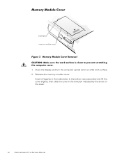
indentation memory module cover 1. then slide the cover in the bottom case assembly and lift the cover slightly; Insert a fingertip in the indentation in the direction indicated by the arrow on a flat work surface. 2. Close the display, and turn the computer upside down on the cover. 14 Dell Latitude CPi A Service Manual Release the memory module cover.
indentation memory module cover 1. then slide the cover in the bottom case assembly and lift the cover slightly; Insert a fingertip in the indentation in the direction indicated by the arrow on a flat work surface. 2. Close the display, and turn the computer upside down on the cover. 14 Dell Latitude CPi A Service Manual Release the memory module cover.
User Manual
Page 21
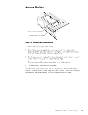
... I/O connector on each of its socket. Do not attempt to the memory module from its socket, gently push outward on the computer's back panel. 3. You can install memory modules only one way. Dell Latitude CPi A Service Manual 15 The memory module rotates upward out of the memory module's two metal retaining clips. Align the notch near the...
... I/O connector on each of its socket. Do not attempt to the memory module from its socket, gently push outward on the computer's back panel. 3. You can install memory modules only one way. Dell Latitude CPi A Service Manual 15 The memory module rotates upward out of the memory module's two metal retaining clips. Align the notch near the...
User Manual
Page 44
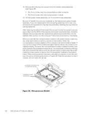
Be sure to transfer the memory module(s) to the system board. Insert the diskette that accompanied the replacement system board assembly into the BIOS of the bottom case assembly. Press the ... seated correctly. Remove the following two screws from the system board assembly (see Figure 28). If one -slot clip shown) processor-module fence holes 38 Dell Latitude CPi A Service Manual Lift the system board assembly out of the replacement system board assembly.
Be sure to transfer the memory module(s) to the system board. Insert the diskette that accompanied the replacement system board assembly into the BIOS of the bottom case assembly. Press the ... seated correctly. Remove the following two screws from the system board assembly (see Figure 28). If one -slot clip shown) processor-module fence holes 38 Dell Latitude CPi A Service Manual Lift the system board assembly out of the replacement system board assembly.

User Manual
Page 50
... latch assemblies removal, 33 module latch assemblies removal, 33 screw identification and tightening, 3 sockets memory module, 15 speakers removal, 34 system board assembly removal, 35 tools, 2 touch-pad interface module removal, 20 travel module removal, 30 palmrest assembly removal, 19 power button removal, 21 preparing to work, 2 ZIF connectors, 4 2 Dell Latitude CPi A Service Manual
... latch assemblies removal, 33 module latch assemblies removal, 33 screw identification and tightening, 3 sockets memory module, 15 speakers removal, 34 system board assembly removal, 35 tools, 2 touch-pad interface module removal, 20 travel module removal, 30 palmrest assembly removal, 19 power button removal, 21 preparing to work, 2 ZIF connectors, 4 2 Dell Latitude CPi A Service Manual


