Service Manual
Page 3
... 1-5 Interrupt Assignments 1-6 Technical Specifications 1-7 Initial User Contact 2-1 Visual Inspection 2-2 Observing the Boot Routine 2-4 Eliminating Resource Conflicts 2-6 Getting Help 2-6 POST Error Codes 3-1 Battery Failure Codes 3-4 System Error Messages 3-5 Running the Dell Diagnostics 3-9 Recommended Tools 4-2 Precautionary Measures 4-2 Screw Identification and Tightening 4-3 ZIF Connectors 4-4 Field-Replaceable Parts and Assemblies 4-5 Removing Field-Replaceable Parts and Assemblies...
... 1-5 Interrupt Assignments 1-6 Technical Specifications 1-7 Initial User Contact 2-1 Visual Inspection 2-2 Observing the Boot Routine 2-4 Eliminating Resource Conflicts 2-6 Getting Help 2-6 POST Error Codes 3-1 Battery Failure Codes 3-4 System Error Messages 3-5 Running the Dell Diagnostics 3-9 Recommended Tools 4-2 Precautionary Measures 4-2 Screw Identification and Tightening 4-3 ZIF Connectors 4-4 Field-Replaceable Parts and Assemblies 4-5 Removing Field-Replaceable Parts and Assemblies...
Service Manual
Page 4
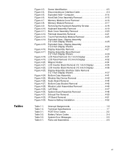
...Figure 3-1. Front View of the Computer 1-2 Back View of the Computer 1-3 Bottom View of the Computer 1-3 Indicator Panel 1-4 Battery Indicator 3-4 Computer Orientation 4-1 Main Battery Assembly Removal 4-3 vi Hard-Disk Drive Assembly 4-15 Memory Module Cover 4-16 Memory Modules 4-17 Keyboard Assembly 4-18 Back Cover... Display Hinge 4-38 Display-Assembly Top Cover 4-39 Bottom Case Assembly 4-40 Modular Bay Devices (Diskette Drive, CD-ROM Drive, Battery, or Travel Module 4-42 Audio Shield 4-43 Audio Board 4-44 Bottom Case Bracket 4-45 Module Latch Assemblies 4-46 Speakers 4-47...
...Figure 3-1. Front View of the Computer 1-2 Back View of the Computer 1-3 Bottom View of the Computer 1-3 Indicator Panel 1-4 Battery Indicator 3-4 Computer Orientation 4-1 Main Battery Assembly Removal 4-3 vi Hard-Disk Drive Assembly 4-15 Memory Module Cover 4-16 Memory Modules 4-17 Keyboard Assembly 4-18 Back Cover... Display Hinge 4-38 Display-Assembly Top Cover 4-39 Bottom Case Assembly 4-40 Modular Bay Devices (Diskette Drive, CD-ROM Drive, Battery, or Travel Module 4-42 Audio Shield 4-43 Audio Board 4-44 Bottom Case Bracket 4-45 Module Latch Assemblies 4-46 Speakers 4-47...
Service Manual
Page 5
... Assemblies Removal 4-46 Left Slider 4-47 System Board Assembly Removal 4-48 Exhaust Fan Removal 4-50 I/R Board Removal 4-51 Reserve Battery Installation 4-52 Table 1-1. Table 1-2. Table 3-2. Interrupt Assignments 1-6 Technical Specifications 1-7 POST Error Codes 3-2 Battery Failure Codes 3-4 System Error Messages 3-5 Parts and Assemblies 4-5 vii Figure 4-3. Figure 4-10. Figure 4-13. Figure 4-18. Figure 4-32. Table...
... Assemblies Removal 4-46 Left Slider 4-47 System Board Assembly Removal 4-48 Exhaust Fan Removal 4-50 I/R Board Removal 4-51 Reserve Battery Installation 4-52 Table 1-1. Table 1-2. Table 3-2. Interrupt Assignments 1-6 Technical Specifications 1-7 POST Error Codes 3-2 Battery Failure Codes 3-4 System Error Messages 3-5 Parts and Assemblies 4-5 vii Figure 4-3. Figure 4-10. Figure 4-13. Figure 4-18. Figure 4-32. Table...
Service Manual
Page 7
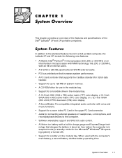
... in suspend mode [or standby mode for a hard-disk drive in the upper PC Card connector. A lithium ion battery with 32 KB of the Dell® Latitude® CP and CPi portable computers. When used with voice and music functions. System Overview 1-1 This chapter provides an overview of ... Windows® 98 operating system] or turned off). A 512-KB or 256-KB pipelined-burst SRAM external cache. Support for a battery in a Dell portable computer, the Latitude CP and CPi include the following new features: A Mobile Intel® Pentium® II microprocessor 233, 266, or 300 MHz or an...
... in suspend mode [or standby mode for a hard-disk drive in the upper PC Card connector. A lithium ion battery with 32 KB of the Dell® Latitude® CP and CPi portable computers. When used with voice and music functions. System Overview 1-1 This chapter provides an overview of ... Windows® 98 operating system] or turned off). A 512-KB or 256-KB pipelined-burst SRAM external cache. Support for a battery in a Dell portable computer, the Latitude CP and CPi include the following new features: A Mobile Intel® Pentium® II microprocessor 233, 266, or 300 MHz or an...
Service Manual
Page 8
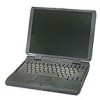
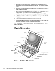
Automatic thermal management that help you conserve battery power. A BIOS that can be upgraded by diskette if required. Hardware and software support for the Dell Latitude C/Port Advanced Port Replicator (APR) and Latitude C/Dock Expansion Station. For a complete list of system ...mouse functionality. display microphone power button keyboard touch pad battery bay touch pad buttons (2) modular bay display latch indicator panel cooling-fan air intake AC adapter connector audio jacks (3) speakers (2) 1-2 Dell Latitude CP and CPi Service Manual Two power management modes...
Automatic thermal management that help you conserve battery power. A BIOS that can be upgraded by diskette if required. Hardware and software support for the Dell Latitude C/Port Advanced Port Replicator (APR) and Latitude C/Dock Expansion Station. For a complete list of system ...mouse functionality. display microphone power button keyboard touch pad battery bay touch pad buttons (2) modular bay display latch indicator panel cooling-fan air intake AC adapter connector audio jacks (3) speakers (2) 1-2 Dell Latitude CP and CPi Service Manual Two power management modes...
Service Manual
Page 9
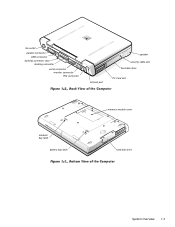
fan outlet parallel connector USB connector docking connector door docking connector serial connector monitor connector PS2 connector infrared port speaker security cable slot hard-disk drive PC Card slot modular bay latch battery bay latch memory module cover hard-disk drive System Overview 1-3
fan outlet parallel connector USB connector docking connector door docking connector serial connector monitor connector PS2 connector infrared port speaker security cable slot hard-disk drive PC Card slot modular bay latch battery bay latch memory module cover hard-disk drive System Overview 1-3
Service Manual
Page 10
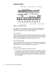
...adapter is providing a maintenance (trickle) charge to indicate that the computer is fully charged, the battery indicator blinks green to keep the battery at full capacity. 1-4 Dell Latitude CP and CPi Service Manual During the normal charging cycle, the indicator remains on , the power ... power indicator is off, the computer is fast-charging. power indicator drive activity indicator battery indicator numbers lock indicator capitals lock indicator scroll lock indicator The Latitude CP or CPi computer has three indicators on the display assembly's indicator panel and three on...
...adapter is providing a maintenance (trickle) charge to indicate that the computer is fully charged, the battery indicator blinks green to keep the battery at full capacity. 1-4 Dell Latitude CP and CPi Service Manual During the normal charging cycle, the indicator remains on , the power ... power indicator is off, the computer is fast-charging. power indicator drive activity indicator battery indicator numbers lock indicator capitals lock indicator scroll lock indicator The Latitude CP or CPi computer has three indicators on the display assembly's indicator panel and three on...
Service Manual
Page 11
...(A modem ring or system alarm event will also turn on the computer.) Pressing the power button for 4 seconds causes the computer to turn on the Latitude CP or CPi computer, C/Dock Expansion Station, or the C/Port APR initiates a change from -disk operation. If the computer is off , pressing the ... computer is in Chapter 3 for Windows 98) (power indicator is in suspend mode (or standby mode for a listing of the keyboard. Refer to "Battery Failure Codes" in suspend-to "POST Error Codes" in suspend mode (or standby mode for a listing of charge remaining. Refer to -disk mode and...
...(A modem ring or system alarm event will also turn on the computer.) Pressing the power button for 4 seconds causes the computer to turn on the Latitude CP or CPi computer, C/Dock Expansion Station, or the C/Port APR initiates a change from -disk operation. If the computer is off , pressing the ... computer is in Chapter 3 for Windows 98) (power indicator is in suspend mode (or standby mode for a listing of the keyboard. Refer to "Battery Failure Codes" in suspend-to "POST Error Codes" in suspend mode (or standby mode for a listing of charge remaining. Refer to -disk mode and...
Service Manual
Page 18
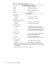
... cycles Temperature range: Charge 0° to 40°C (32° to 104°F) Storage 20° to 60°C (-4° to 140°F) 3 Battery performance features such as charge time and life span can vary according to the conditions under which the computer and battery are used. 1-12 Dell Latitude CP and CPi Service Manual
... cycles Temperature range: Charge 0° to 40°C (32° to 104°F) Storage 20° to 60°C (-4° to 140°F) 3 Battery performance features such as charge time and life span can vary according to the conditions under which the computer and battery are used. 1-12 Dell Latitude CP and CPi Service Manual
Service Manual
Page 19
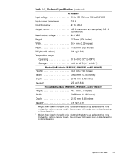
... or less, depending on its configuration. Your computer might weigh more or less, depending on its configuration. 5 Weight shown is with a hard-disk drive, a battery in the battery bay, a diskette drive in the modular bay, and one memory module. System Overview 1-13 Input voltage 90 to 135 VAC and 164 to 264... 44.1 mm (1.74 inches) Width 306.8 mm (12.08 inches) Depth 241.0 mm (9.49 inches) Weight5 2.8 kg (6.2 lb) 4 Weight shown is with a hard-disk drive, a battery in the battery bay, a diskette drive in the modular bay, and one memory module.
... or less, depending on its configuration. Your computer might weigh more or less, depending on its configuration. 5 Weight shown is with a hard-disk drive, a battery in the battery bay, a diskette drive in the modular bay, and one memory module. System Overview 1-13 Input voltage 90 to 135 VAC and 164 to 264... 44.1 mm (1.74 inches) Width 306.8 mm (12.08 inches) Depth 241.0 mm (9.49 inches) Weight5 2.8 kg (6.2 lb) 4 Weight shown is with a hard-disk drive, a battery in the battery bay, a diskette drive in the modular bay, and one memory module.
Service Manual
Page 20
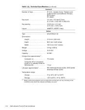
Your computer might weigh more or less, depending on its configuration. 7 Measured with a hard-disk drive, a battery in the battery bay, a diskette drive in head-parked position. 1-14 Dell Latitude CP and CPi Service Manual Height 38.6 mm (1.52 inches) Width 306.0 mm (12.05 inches) Depth 241.0 mm (9.49 inches) Weight6 2.6 kg (5.8 lb) Temperature: Operating...
Your computer might weigh more or less, depending on its configuration. 7 Measured with a hard-disk drive, a battery in the battery bay, a diskette drive in head-parked position. 1-14 Dell Latitude CP and CPi Service Manual Height 38.6 mm (1.52 inches) Width 306.0 mm (12.05 inches) Depth 241.0 mm (9.49 inches) Weight6 2.6 kg (5.8 lb) Temperature: Operating...
Service Manual
Page 22
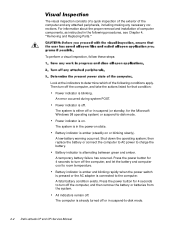
... and any attached peripherals, including making any necessary corrections. The system is connected to -disk mode. 2-2 Dell Latitude CP and CPi Service Manual A low-battery warning occurred. Battery indicator is amber and blinking rapidly when the power switch is pressed or the AC adapter is either off...take the actions listed for the Microsoft Windows 98 operating system) or suspend-to turn off the computer, and then remove the battery or batteries from the system. The computer is alternating between green and amber. Power indicator is on or blinking slowly). All indicators remain...
... and any attached peripherals, including making any necessary corrections. The system is connected to -disk mode. 2-2 Dell Latitude CP and CPi Service Manual A low-battery warning occurred. Battery indicator is amber and blinking rapidly when the power switch is pressed or the AC adapter is either off...take the actions listed for the Microsoft Windows 98 operating system) or suspend-to turn off the computer, and then remove the battery or batteries from the system. The computer is alternating between green and amber. Power indicator is on or blinking slowly). All indicators remain...
Service Manual
Page 23
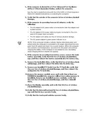
... cooled to room temperature, reconnect it to the computer's DC power input connector. NOTE: If the computer's battery indicator flashes alternately green and amber while the computer is not allowed to cool, the battery stops charging before it to both the adapter and a power source. If the computer is connected to AC... APR or C/Dock Expansion Station for detailed instructions on . The AC adapter's DC power cable is properly connected to AC power and continue charging the battery.
... cooled to room temperature, reconnect it to the computer's DC power input connector. NOTE: If the computer's battery indicator flashes alternately green and amber while the computer is not allowed to cool, the battery stops charging before it to both the adapter and a power source. If the computer is connected to AC... APR or C/Dock Expansion Station for detailed instructions on . The AC adapter's DC power cable is properly connected to AC power and continue charging the battery.
Service Manual
Page 25
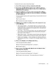
... light up in response to data being transferred to or from the drives. Troubleshoot the power subsystem. Drive access indicator - Battery failure codes - No. Initial Procedures 2-5 If a system error message displays, refer to the next section, "Eliminating Resource Conflicts." See "Running the... in Chapter 3. Does the Diagnostics Menu display? Does the Diagnostics Menu display? Proceed to step 4. Error codes - See "Running the Dell Diagnostics" in Chapter 3. No. Yes. If the indicator fails to light during the boot routine, refer to Table 3-2. Proceed to step ...
... light up in response to data being transferred to or from the drives. Troubleshoot the power subsystem. Drive access indicator - Battery failure codes - No. Initial Procedures 2-5 If a system error message displays, refer to the next section, "Eliminating Resource Conflicts." See "Running the... in Chapter 3. Does the Diagnostics Menu display? Does the Diagnostics Menu display? Proceed to step 4. Error codes - See "Running the Dell Diagnostics" in Chapter 3. No. Yes. If the indicator fails to light during the boot routine, refer to Table 3-2. Proceed to step ...
Service Manual
Page 27
... the source of the problem. If a faulty computer does not display a POST error code or system error message to indicate a failure, use the Dell Diagnostics to help you identify a faulty component or assembly. The tables in this chapter. These "flash" codes are the same as their probable causes....the system board or other corrective actions before the computer can occur during computer startup or, in this chapter list POST error codes, battery failure codes, and system error messages, as well as the audible "beep" codes used by the Dell Latitude XPi portable computer, for instance.
... the source of the problem. If a faulty computer does not display a POST error code or system error message to indicate a failure, use the Dell Diagnostics to help you identify a faulty component or assembly. The tables in this chapter. These "flash" codes are the same as their probable causes....the system board or other corrective actions before the computer can occur during computer startup or, in this chapter list POST error codes, battery failure codes, and system error messages, as well as the audible "beep" codes used by the Dell Latitude XPi portable computer, for instance.
Service Manual
Page 29
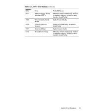
4-3-1 4-3-3 4-3-4 4-4-1 5-1-2 Memory failure above address 0FFFFh Timer chip counter 2 failure Time-of-day clock stopped Serial port failure No usable memory Memory module improperly seated or system memory controller faulty (system board faulty) System board faulty Reserve battery faulty or system board faulty System board faulty Memory module improperly seated or system memory controller faulty (system board faulty) System Error Messages 3-3
4-3-1 4-3-3 4-3-4 4-4-1 5-1-2 Memory failure above address 0FFFFh Timer chip counter 2 failure Time-of-day clock stopped Serial port failure No usable memory Memory module improperly seated or system memory controller faulty (system board faulty) System board faulty Reserve battery faulty or system board faulty System board faulty Memory module improperly seated or system memory controller faulty (system board faulty) System Error Messages 3-3
Service Manual
Page 30
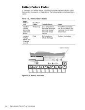
Indicator flashes alternately green and amber. abnormal discharge; Replace the battery. battery indicator 3-4 Dell Latitude CP and CPi Service Manual abnormal charge current Fatal Cell imbalance; In the event of a battery failure, the battery indicator displays indicator codes that identify the severity of the problem. Temporary Over temperature; critical discharge Turn off the computer and let the battery and computer cool to room temperature. The following table lists these failure codes. abnormal charge; Indicator flashes amber four times per second.
Indicator flashes alternately green and amber. abnormal discharge; Replace the battery. battery indicator 3-4 Dell Latitude CP and CPi Service Manual abnormal charge current Fatal Cell imbalance; In the event of a battery failure, the battery indicator displays indicator codes that identify the severity of the problem. Temporary Over temperature; critical discharge Turn off the computer and let the battery and computer cool to room temperature. The following table lists these failure codes. abnormal charge; Indicator flashes amber four times per second.
Service Manual
Page 33
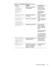
... 3-7 The software in keyboard, keyboard faulty. please run System Setup program System Setup contains invalid settings. Cable or connector loose, or keyboard faulty. NVRAM reserve battery weak or depleted. Keyboard control- Invalid configuration information - For external keyboard or keypad, cable or connector loose or keyboard faulty.
... 3-7 The software in keyboard, keyboard faulty. please run System Setup program System Setup contains invalid settings. Cable or connector loose, or keyboard faulty. NVRAM reserve battery weak or depleted. Keyboard control- Invalid configuration information - For external keyboard or keypad, cable or connector loose or keyboard faulty.
Service Manual
Page 35
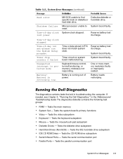
... and Troubleshooting Guide. If needed, see Chapter 4, "Running the Dell Diagnostics," in RTC does not match system clock. Tests the video subsystem Keyboard - Tests the serial communication port Parallel Ports - Battery needs recharging. Seek error Shutdown failure Time-of-day clock lost ...that aid in protected mode Warning! Tests the keyboard subsystem Mouse - Timer chip counter 2 failed Unexpected interrupt in troubleshooting the computer. Battery is critically low. System board faulty. Tests the main memory System Set - One or more memory module(s) faulty or improperly seated...
... and Troubleshooting Guide. If needed, see Chapter 4, "Running the Dell Diagnostics," in RTC does not match system clock. Tests the video subsystem Keyboard - Tests the serial communication port Parallel Ports - Battery needs recharging. Seek error Shutdown failure Time-of-day clock lost ...that aid in protected mode Warning! Tests the keyboard subsystem Mouse - Timer chip counter 2 failed Unexpected interrupt in troubleshooting the computer. Battery is critically low. System board faulty. Tests the main memory System Set - One or more memory module(s) faulty or improperly seated...

Service Manual
Page 39
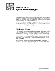
Slide the battery bay latch away from the center of the battery bay (see Figure 4-2). battery bay latch battery The illustrations in the illustration to the graphic in the following removal procedures provide the correct screw length as part of the screw's label. Match the actual screw to check for that length screw is also included in the illustration. A graphic for correct length. Removing and Replacing Parts 4-3 Then slide the battery out of the computer.
Slide the battery bay latch away from the center of the battery bay (see Figure 4-2). battery bay latch battery The illustrations in the illustration to the graphic in the following removal procedures provide the correct screw length as part of the screw's label. Match the actual screw to check for that length screw is also included in the illustration. A graphic for correct length. Removing and Replacing Parts 4-3 Then slide the battery out of the computer.

