Service Manual
Page 5
... Specifications 1-7 POST Error Codes 3-2 Battery Failure Codes 3-4 System Error Messages 3-5 Parts and Assemblies 4-5 vii Figure 4-8. Figure 4-12. Figure 4-32. Screw Identification 4-3 Disconnecting an Interface Cable 4-4 Exploded View-Computer 4-14 Hard-Disk Drive Assembly Removal 4-15 Memory Module Cover Removal 4-16 Memory Module Removal 4-17 Removing the Keyboard Assembly Screws 4-18 Keyboard Assembly Removal 4-19 Back Cover Assembly Removal 4-20 Palmrest Assembly Removal 4-21 Touch-Pad Interface Module Removal 4-23 Exploded View-Display Assembly (12.1-Inch Display...
... Specifications 1-7 POST Error Codes 3-2 Battery Failure Codes 3-4 System Error Messages 3-5 Parts and Assemblies 4-5 vii Figure 4-8. Figure 4-12. Figure 4-32. Screw Identification 4-3 Disconnecting an Interface Cable 4-4 Exploded View-Computer 4-14 Hard-Disk Drive Assembly Removal 4-15 Memory Module Cover Removal 4-16 Memory Module Removal 4-17 Removing the Keyboard Assembly Screws 4-18 Keyboard Assembly Removal 4-19 Back Cover Assembly Removal 4-20 Palmrest Assembly Removal 4-21 Touch-Pad Interface Module Removal 4-23 Exploded View-Display Assembly (12.1-Inch Display...
Service Manual
Page 7
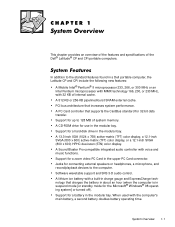
... bay. Software wavetable support and SRS 3-D audio control. Support for 32-bit data transfer. In addition to 128 MB of system memory. When used with voice and music functions. A CD-ROM drive for a battery in the upper PC Card connector. System Overview 1-1 A Sound Blaster Pro-compatible integrated audio controller with the computer's main battery, a second battery doubles battery operating time. A lithium ion battery with a built-in a Dell portable computer, the Latitude CP and CPi...
... bay. Software wavetable support and SRS 3-D audio control. Support for 32-bit data transfer. In addition to 128 MB of system memory. When used with voice and music functions. A CD-ROM drive for a battery in the upper PC Card connector. System Overview 1-1 A Sound Blaster Pro-compatible integrated audio controller with the computer's main battery, a second battery doubles battery operating time. A lithium ion battery with a built-in a Dell portable computer, the Latitude CP and CPi...
Service Manual
Page 8
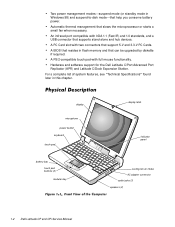
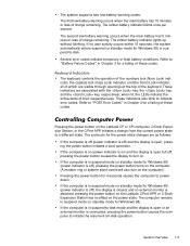
... starts a small fan when necessary. display microphone power button keyboard touch pad battery bay touch pad buttons (2) modular bay display latch indicator panel cooling-fan air intake AC adapter connector audio jacks (3) speakers (2) 1-2 Dell Latitude CP and CPi Service Manual A PC Card slot with two connectors that help you conserve battery power. Hardware and software support for the Dell Latitude C/Port Advanced Port Replicator (APR) and Latitude C/Dock Expansion Station. Two power management modessuspend mode (or standby mode in Windows 98) and suspend-to-disk mode...
... starts a small fan when necessary. display microphone power button keyboard touch pad battery bay touch pad buttons (2) modular bay display latch indicator panel cooling-fan air intake AC adapter connector audio jacks (3) speakers (2) 1-2 Dell Latitude CP and CPi Service Manual A PC Card slot with two connectors that help you conserve battery power. Hardware and software support for the Dell Latitude C/Port Advanced Port Replicator (APR) and Latitude C/Dock Expansion Station. Two power management modessuspend mode (or standby mode in Windows 98) and suspend-to-disk mode...
Service Manual
Page 10
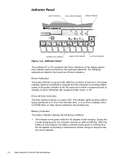
...ROM drive, or other device installed in suspend mode (or standby mode for Windows 98), suspend-to indicate that the AC adapter is a green LED. The battery indicator displays the following subsections describe the functions of these indicators. After the battery is fully charged, the battery indicator blinks green to indicate that the computer is being transferred to or from the hard-disk drive, or to keep the battery at full capacity. 1-4 Dell Latitude CP and CPi Service Manual power indicator drive activity indicator battery indicator numbers lock indicator capitals lock indicator...
...ROM drive, or other device installed in suspend mode (or standby mode for Windows 98), suspend-to indicate that the AC adapter is a green LED. The battery indicator displays the following subsections describe the functions of these indicators. After the battery is fully charged, the battery indicator blinks green to indicate that the computer is being transferred to or from the hard-disk drive, or to keep the battery at full capacity. 1-4 Dell Latitude CP and CPi Service Manual power indicator drive activity indicator battery indicator numbers lock indicator capitals lock indicator...
Service Manual
Page 11
... respective keys. The computer remains in Chapter 3 for Windows 98) or suspend-to indicate error codes. Pressing the power button on the computer.) Pressing the power button for a listing of the keyboard. If the computer is off ), the display is closed, and no external monitor is in suspend-to turn on the Latitude CP or CPi computer, C/Dock Expansion Station, or the C/Port APR initiates a change from -disk operation. The amber battery indicator lights...
... respective keys. The computer remains in Chapter 3 for Windows 98) or suspend-to indicate error codes. Pressing the power button on the computer.) Pressing the power button for a listing of the keyboard. If the computer is off ), the display is closed, and no external monitor is in suspend-to turn on the Latitude CP or CPi computer, C/Dock Expansion Station, or the C/Port APR initiates a change from -disk operation. The amber battery indicator lights...
Service Manual
Page 12
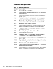
... Generated by the CD-ROM drive in serial port or infrared port is configured for COM1 (the default) or COM3 Available for use by the audio controller Generated by the diskette drive controller to indicate that the diskette drive requires the attention of the microprocessor Available for use by the internal coprocessor Generated by the hard-disk drive to indicate that it requires the attention of the microprocessor 1-6 Dell Latitude CP and CPi Service Manual
... Generated by the CD-ROM drive in serial port or infrared port is configured for COM1 (the default) or COM3 Available for use by the audio controller Generated by the diskette drive controller to indicate that the diskette drive requires the attention of the microprocessor Available for use by the internal coprocessor Generated by the hard-disk drive to indicate that it requires the attention of the microprocessor 1-6 Dell Latitude CP and CPi Service Manual
Service Manual
Page 14
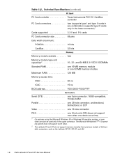
... BIOS address F000:0000-F000:FFFF Serial (DTE one 9-pin connector; 16550-compatible, 16-byte buffer Parallel one device at a time) 1 On systems using the Microsoft Windows 95 or Windows 98 operating system, a zoom video card can be used only in the upper connector. The Microsoft Windows NT ® 4.0 operating system does not support zoom video. 2 The Latitude CP and CPi do not support memory modules from previous models of Dell...
... BIOS address F000:0000-F000:FFFF Serial (DTE one 9-pin connector; 16550-compatible, 16-byte buffer Parallel one device at a time) 1 On systems using the Microsoft Windows 95 or Windows 98 operating system, a zoom video card can be used only in the upper connector. The Microsoft Windows NT ® 4.0 operating system does not support zoom video. 2 The Latitude CP and CPi do not support memory modules from previous models of Dell...
Service Manual
Page 21
... her to the appropriate user documentation for troubleshooting the computer. Proceed to the next section, "Visual Inspection." Proceed to the next section, "Visual Inspection." Instruct the user in the online Dell Latitude CP and CPi User's Guide. Initial Procedures 2-1 This chapter describes initial procedures that you first contact a user who has a computer problem, ask the user to describe the problem and the conditions...
... her to the appropriate user documentation for troubleshooting the computer. Proceed to the next section, "Visual Inspection." Proceed to the next section, "Visual Inspection." Instruct the user in the online Dell Latitude CP and CPi User's Guide. Initial Procedures 2-1 This chapter describes initial procedures that you first contact a user who has a computer problem, ask the user to describe the problem and the conditions...
Service Manual
Page 22
... -disk mode. 2-2 Dell Latitude CP and CPi Service Manual For information about the proper removal and installation of the computer and any attached peripherals, including making any necessary corrections. A low-battery warning occurred. Shut down the operating system; An error occurred during system POST. All indicators remain off the computer, and then remove the battery or batteries from the system. Then turn off or in the power-on . then replace...
... -disk mode. 2-2 Dell Latitude CP and CPi Service Manual For information about the proper removal and installation of the computer and any attached peripherals, including making any necessary corrections. A low-battery warning occurred. Shut down the operating system; An error occurred during system POST. All indicators remain off the computer, and then remove the battery or batteries from the system. Then turn off or in the power-on . then replace...
Service Manual
Page 24
... the diskette and always use a backup copy when servicing a user's computer. For instructions, see "Before You Start Testing" in the documentation for any indications of problems. NOTE: To prevent possible damage to the video connector on the computer's I /O panel. The captive screws that secure the connectors at each end of the Dell Latitude CP Reference and Troubleshooting Guide. 2-4 Dell Latitude CP and CPi Service Manual The monitor's controls are set according to the...
... the diskette and always use a backup copy when servicing a user's computer. For instructions, see "Before You Start Testing" in the documentation for any indications of problems. NOTE: To prevent possible damage to the video connector on the computer's I /O panel. The captive screws that secure the connectors at each end of the Dell Latitude CP Reference and Troubleshooting Guide. 2-4 Dell Latitude CP and CPi Service Manual The monitor's controls are set according to the...
Service Manual
Page 31
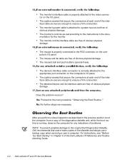
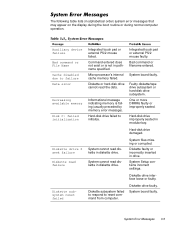
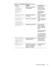
... external PS/2 mouse faulty. Hard-disk drive damaged. Diskette drive faulty. Hard-disk drive improperly seated in diskette drive. System cannot read failure Diskette subsystem reset failed Integrated touch pad or external PS/2 mouse failed. System Setup contains incorrect settings. System board faulty. Microprocessor's internal cache memory failed. System board faulty. Informational message indicating memory is not in alphabetical order) system error messages that may appear on the display during the boot routine or during normal computer operation...
... external PS/2 mouse faulty. Hard-disk drive damaged. Diskette drive faulty. Hard-disk drive improperly seated in diskette drive. System cannot read failure Diskette subsystem reset failed Integrated touch pad or external PS/2 mouse failed. System Setup contains incorrect settings. System board faulty. Microprocessor's internal cache memory failed. System board faulty. Informational message indicating memory is not in alphabetical order) system error messages that may appear on the display during the boot routine or during normal computer operation...

Service Manual
Page 32
Computer cannot enable protective mode. Installed hard-disk drive not compatible with computer. Hard-disk drive faulty. 3-6 Dell Latitude CP and CPi Service Manual Amount of memory recorded in NVRAM does not match memory installed in the diskette drive. Message indicates system failure. The CD-ROM drive does not respond to commands from the computer. System board faulty. PC Card software faulty or incorrectly installed. System board faulty. System board faulty. Diskette writeprotected. System board faulty. Hard-disk drive or controller not responding...
Computer cannot enable protective mode. Installed hard-disk drive not compatible with computer. Hard-disk drive faulty. 3-6 Dell Latitude CP and CPi Service Manual Amount of memory recorded in NVRAM does not match memory installed in the diskette drive. Message indicates system failure. The CD-ROM drive does not respond to commands from the computer. System board faulty. PC Card software faulty or incorrectly installed. System board faulty. System board faulty. Diskette writeprotected. System board faulty. Hard-disk drive or controller not responding...
Service Manual
Page 33
... keypad, cable or connector loose or keyboard faulty. please run System Setup program System Setup contains invalid settings. Keyboard controller not ler failure responding. The software in keyboard, keyboard faulty. Keyboard clock line failure Keyboard data line failure Keyboard stuck key failure Keyboard not responding. Installed memory module faulty or improperly seated. For built-in use conflicts with the operating system, an application program, or a utility. Faulty application program. Invalid configuration information - Keyboard control-
... keypad, cable or connector loose or keyboard faulty. please run System Setup program System Setup contains invalid settings. Keyboard controller not ler failure responding. The software in keyboard, keyboard faulty. Keyboard clock line failure Keyboard data line failure Keyboard stuck key failure Keyboard not responding. Installed memory module faulty or improperly seated. For built-in use conflicts with the operating system, an application program, or a utility. Faulty application program. Invalid configuration information - Keyboard control-

Service Manual
Page 34
... value expecting value No boot device available No boot sector on diskette or hard-disk drive. 3-8 Dell Latitude CP and CPi Service Manual System board faulty. Memory data line failure at address, read value expecting value Memory not operating properly. No operating system files on harddisk drive. Optional ROM in external device failed. No boot sector on hard-disk drive or diskette. ROM in external device faulty. Installed memory module faulty or improperly seated. No boot device available. Operating system boot files missing or corrupted...
... value expecting value No boot device available No boot sector on diskette or hard-disk drive. 3-8 Dell Latitude CP and CPi Service Manual System board faulty. Memory data line failure at address, read value expecting value Memory not operating properly. No operating system files on harddisk drive. Optional ROM in external device failed. No boot sector on hard-disk drive or diskette. ROM in external device faulty. Installed memory module faulty or improperly seated. No boot device available. Operating system boot files missing or corrupted...
Service Manual
Page 36
...," in the Reference and Troubleshooting Guide for information on the screen telling you do not have a diskette-drive cable to perform the following options or exit to isolate a failure Run All Tests - If no errors are found in the C/Port APR or the C/Dock Expansion Station Audio - Tests a particular area or subsystem 3-10 Dell Latitude CP and CPi Service Manual Tests the built-in...
...," in the Reference and Troubleshooting Guide for information on the screen telling you do not have a diskette-drive cable to perform the following options or exit to isolate a failure Run All Tests - If no errors are found in the C/Port APR or the C/Dock Expansion Station Audio - Tests a particular area or subsystem 3-10 Dell Latitude CP and CPi Service Manual Tests the built-in...
Service Manual
Page 89
...3-4 battery indicator, 1-4 boot routine observing when troubleshooting, 2-4 bottom case assembly components, 4-40 illustrated, 4-41 bottom case bracket removal, 4-45 cables display-assembly interface cable, removal, 4-37 CD-ROM drive removal, 4-42 Dell Diagnostics, 3-9 diskette drive removal, 4-42 display assembly bezel, removal, 4-29 components, 4-25 illustrated, 4-25, 4-26 interface cable, removal, 4-37 removal, 4-27 top cover, removal, 4-39 drive activity indicator, 1-4 error codes battery failure, 3-4 POST, 3-1 error messages, system, 3-5 ESD, 4-2 exhaust fan removal, 4-50 external visual...
...3-4 battery indicator, 1-4 boot routine observing when troubleshooting, 2-4 bottom case assembly components, 4-40 illustrated, 4-41 bottom case bracket removal, 4-45 cables display-assembly interface cable, removal, 4-37 CD-ROM drive removal, 4-42 Dell Diagnostics, 3-9 diskette drive removal, 4-42 display assembly bezel, removal, 4-29 components, 4-25 illustrated, 4-25, 4-26 interface cable, removal, 4-37 removal, 4-27 top cover, removal, 4-39 drive activity indicator, 1-4 error codes battery failure, 3-4 POST, 3-1 error messages, system, 3-5 ESD, 4-2 exhaust fan removal, 4-50 external visual...
Service Manual
Page 90
field-replaceable parts and assemblies illustrated, 4-14 list of, 4-5 hard-disk drive assembly removal, 4-15 help getting, 2-6 I/O panel, 1-3 I/R board removal, 4-51 indicator panel, 1-4 initial procedures system error messages, 3-5 troubleshooting, 2-1 initialization error messages, 3-10 interrupt assignments list of, 1-6 keyboard assembly removal, 4-18 keyboard indicators, 1-5 LCD display hinge removal, 4-38 LCD inverter board removal, 4-35, 4-36 2 Dell Latitude CP and CPi Service Manual LCD panel removal, 4-31, 4-32 LEDs, 1-4 low-battery warnings, 1-4 main battery assembly removal, ...
field-replaceable parts and assemblies illustrated, 4-14 list of, 4-5 hard-disk drive assembly removal, 4-15 help getting, 2-6 I/O panel, 1-3 I/R board removal, 4-51 indicator panel, 1-4 initial procedures system error messages, 3-5 troubleshooting, 2-1 initialization error messages, 3-10 interrupt assignments list of, 1-6 keyboard assembly removal, 4-18 keyboard indicators, 1-5 LCD display hinge removal, 4-38 LCD inverter board removal, 4-35, 4-36 2 Dell Latitude CP and CPi Service Manual LCD panel removal, 4-31, 4-32 LEDs, 1-4 low-battery warnings, 1-4 main battery assembly removal, ...
Replacement Instructions
Page 23
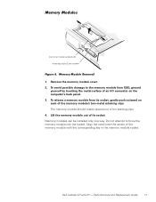
... of the memory module with the corresponding key in the memory module socket. Remove the memory module cover. 2. Do not attempt to the memory module from its socket, gently push outward on the computer's back panel. 3. Parts Removal and Replacement Guide 17 Align the notch near the center of the memory module's two metal retaining clips. Memory modules can be installed only one way. memory module sockets (2) retaining clips (2 per socket) 1. Dell Latitude CP and CPi...
... of the memory module with the corresponding key in the memory module socket. Remove the memory module cover. 2. Do not attempt to the memory module from its socket, gently push outward on the computer's back panel. 3. Parts Removal and Replacement Guide 17 Align the notch near the center of the memory module's two metal retaining clips. Memory modules can be installed only one way. memory module sockets (2) retaining clips (2 per socket) 1. Dell Latitude CP and CPi...
Replacement Instructions
Page 37
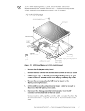
... the LCD panel power cable. 6. Lift the LCD inverter board and inverter board shield far enough to the display-assembly top cover. 5. Dell Latitude CP and CPi - NOTE: When replacing the LCD panel, ensure that the tabs on the underside of the LCD panel. Lift the upper edge of the LCD panel. 3. Disconnect the display-assembly interface cable from the ZIF connector on the LCD interface cable itself. Remove the display assembly bezel. 2. Parts Removal and Replacement Guide 31...
... the LCD panel power cable. 6. Lift the LCD inverter board and inverter board shield far enough to the display-assembly top cover. 5. Dell Latitude CP and CPi - NOTE: When replacing the LCD panel, ensure that the tabs on the underside of the LCD panel. Lift the upper edge of the LCD panel. 3. Disconnect the display-assembly interface cable from the ZIF connector on the LCD interface cable itself. Remove the display assembly bezel. 2. Parts Removal and Replacement Guide 31...
Replacement Instructions
Page 52
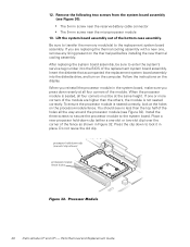
... on the processor-module fence. 12. Lift the system board assembly out of the fence as shown in place. Parts Removal and Replacement Guide Place a new processor hold -down clip (either a one -slot clip shown) processor-module fence holes 46 Dell Latitude CP and CPi - If you press down to enter the system's service tag number into the diskette drive, and turn on the display. Do not reuse...
... on the processor-module fence. 12. Lift the system board assembly out of the fence as shown in place. Parts Removal and Replacement Guide Place a new processor hold -down clip (either a one -slot clip shown) processor-module fence holes 46 Dell Latitude CP and CPi - If you press down to enter the system's service tag number into the diskette drive, and turn on the display. Do not reuse...


