Service Manual
Page 6
... 45 Removing the Hybrid Cooling Fan 46 Microprocessor Module 47 Removing the Microprocessor Module 47 Replacing the Microprocessor Module 48 Reserve Battery 49 Removing the Reserve Battery 49 Replacing the Reserve Battery 50 Speaker Assemblies 50 Removing the Speaker Assemblies 51 Replacing the Speaker Assembly 53 System Board Assembly 53 Removing the System...
... 45 Removing the Hybrid Cooling Fan 46 Microprocessor Module 47 Removing the Microprocessor Module 47 Replacing the Microprocessor Module 48 Reserve Battery 49 Removing the Reserve Battery 49 Replacing the Reserve Battery 50 Speaker Assemblies 50 Removing the Speaker Assemblies 51 Replacing the Speaker Assembly 53 System Board Assembly 53 Removing the System...
Service Manual
Page 7
Battery and Modular Bay Latch Assemblies 57 Removing the Battery and Modular Bay Latch Assemblies . . . . 57 Index 59 Contents 7
Battery and Modular Bay Latch Assemblies 57 Removing the Battery and Modular Bay Latch Assemblies . . . . 57 Index 59 Contents 7
Service Manual
Page 10
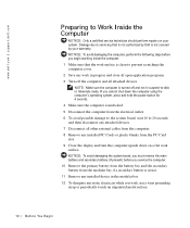
... and the secondary battery from the PC Card slot. 9 Close the display and turn the computer upside down the computer using the computer's operating system, press and hold the power button for 4 seconds. 4 Make sure the computer is not covered by Dell is undocked. 5 Disconnect the computer from the electrical outlet. 6 To...
... and the secondary battery from the PC Card slot. 9 Close the display and turn the computer upside down the computer using the computer's operating system, press and hold the power button for 4 seconds. 4 Make sure the computer is not covered by Dell is undocked. 5 Disconnect the computer from the electrical outlet. 6 To...
Service Manual
Page 11
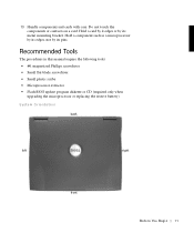
... • Small plastic scribe • Microprocessor extractor • Flash BIOS update program diskette or CD (required only when upgrading the microprocessor or replacing the reserve battery) System Orientation back left right front B e fo re You Be gin 11 Do not touch the components or contacts on a card. Hold a component such as...
... • Small plastic scribe • Microprocessor extractor • Flash BIOS update program diskette or CD (required only when upgrading the microprocessor or replacing the reserve battery) System Orientation back left right front B e fo re You Be gin 11 Do not touch the components or contacts on a card. Hold a component such as...
Service Manual
Page 15
SECTION 2 Removing and Replacing Parts Components Hard Drive Memory Module Mini-PCI Card Assembly Keyboard Assembly Removing the Display Assembly Display Assembly Latch Hinge Covers Palmrest Assembly Microprocessor Thermal Cooling Assembly Hybrid Cooling Fan Microprocessor Module Reserve Battery Speaker Assemblies System Board Assembly Battery and Modular Bay Latch Assemblies www.dell.com | support.dell.com
SECTION 2 Removing and Replacing Parts Components Hard Drive Memory Module Mini-PCI Card Assembly Keyboard Assembly Removing the Display Assembly Display Assembly Latch Hinge Covers Palmrest Assembly Microprocessor Thermal Cooling Assembly Hybrid Cooling Fan Microprocessor Module Reserve Battery Speaker Assemblies System Board Assembly Battery and Modular Bay Latch Assemblies www.dell.com | support.dell.com
Service Manual
Page 16
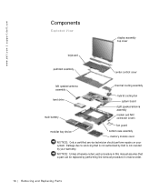
www.dell.com | support.dell.com Components Exploded View display-assembly top cover keyboard palmrest assembly center control cover left speaker/antenna assembly hard drive main battery thermal cooling assembly hybrid cooling fan system board right speaker/antenna assembly modem and NIC connector covers... should perform repairs on your warranty. NOTICE: Unless otherwise noted, each procedure in this manual assumes that is not authorized by Dell is not covered by performing the removal procedure in reverse order. 16 Removi ng and Replacing Parts Damage due to servicing that ...
www.dell.com | support.dell.com Components Exploded View display-assembly top cover keyboard palmrest assembly center control cover left speaker/antenna assembly hard drive main battery thermal cooling assembly hybrid cooling fan system board right speaker/antenna assembly modem and NIC connector covers... should perform repairs on your warranty. NOTICE: Unless otherwise noted, each procedure in this manual assumes that is not authorized by Dell is not covered by performing the removal procedure in reverse order. 16 Removi ng and Replacing Parts Damage due to servicing that ...

Service Manual
Page 17
... M3 x 5-mm screw hard drive door Removing the Hard Drive NOTICE: Disconnect the computer and any attached devices from electrical outlets, and remove any installed batteries. NOTICE: To avoid ESD, ground yourself by using a wrist grounding strap or by its edges (do not squeeze the top of the hard drive case...
... M3 x 5-mm screw hard drive door Removing the Hard Drive NOTICE: Disconnect the computer and any attached devices from electrical outlets, and remove any installed batteries. NOTICE: To avoid ESD, ground yourself by using a wrist grounding strap or by its edges (do not squeeze the top of the hard drive case...
Service Manual
Page 18
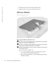
.... Memory Module Memory Module Cover Removing the Memory Module Cover NOTICE: Disconnect the computer and any attached devices from electrical outlets, and remove any installed batteries. www.dell.com | support.dell.com 2 Push down on the computer.
.... Memory Module Memory Module Cover Removing the Memory Module Cover NOTICE: Disconnect the computer and any attached devices from electrical outlets, and remove any installed batteries. www.dell.com | support.dell.com 2 Push down on the computer.
Service Manual
Page 19
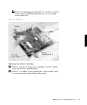
NOTE: The screw labeled with the "circle K" in the middle of the memory module cover secures the keyboard assembly and does not secure the memory module cover. NOTICE: To avoid ESD, ground yourself by using a wrist grounding strap or by touching an unpainted metal surface on the computer. Memory Modules JDIM 1 JDIM 2 inner tabs (2 per socket) memory module sockets (2) Removing the Memory Modules NOTICE: Disconnect the computer and any attached devices from electrical outlets, and remove any installed batteries. Removing and Repl aci ng Part s 19
NOTE: The screw labeled with the "circle K" in the middle of the memory module cover secures the keyboard assembly and does not secure the memory module cover. NOTICE: To avoid ESD, ground yourself by using a wrist grounding strap or by touching an unpainted metal surface on the computer. Memory Modules JDIM 1 JDIM 2 inner tabs (2 per socket) memory module sockets (2) Removing the Memory Modules NOTICE: Disconnect the computer and any attached devices from electrical outlets, and remove any installed batteries. Removing and Repl aci ng Part s 19
Service Manual
Page 22
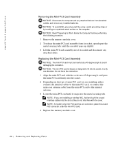
...release the mini-PCI card assembly from its socket, spread apart the metal securing tabs until it snaps into its socket and disconnect any installed batteries. NOTICE: The mini-PCI card is keyed, or designed to the internal antenna. 3 Lower the mini-PCI card until the assembly pops up...place the unused NIC connector under the mini-PCI card. 4 Replace the memory module cover. 22 Removi ng and Replacing Parts www.dell.com | support.dell.com Removing the Mini-PCI Card Assembly NOTICE: Disconnect the computer and any attached devices from electrical outlets, and remove any attached cables...
...release the mini-PCI card assembly from its socket, spread apart the metal securing tabs until it snaps into its socket and disconnect any installed batteries. NOTICE: The mini-PCI card is keyed, or designed to the internal antenna. 3 Lower the mini-PCI card until the assembly pops up...place the unused NIC connector under the mini-PCI card. 4 Replace the memory module cover. 22 Removi ng and Replacing Parts www.dell.com | support.dell.com Removing the Mini-PCI Card Assembly NOTICE: Disconnect the computer and any attached devices from electrical outlets, and remove any attached cables...

Service Manual
Page 23
... devices from the holes labeled "circle K." 3 Turn the computer over , and remove the five M2.5 x 12-mm screws from electrical outlets, and remove any installed batteries. NOTICE: Read "Preparing to replace. NOTICE: To avoid ESD, ground yourself by using a wrist grounding strap or by touching an unpainted metal surface on the...
... devices from the holes labeled "circle K." 3 Turn the computer over , and remove the five M2.5 x 12-mm screws from electrical outlets, and remove any installed batteries. NOTICE: Read "Preparing to replace. NOTICE: To avoid ESD, ground yourself by using a wrist grounding strap or by touching an unpainted metal surface on the...
Service Manual
Page 26
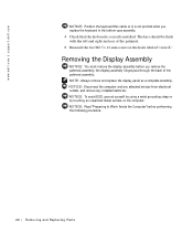
www.dell.com | support.dell.com NOTICE: Position the keyboard flex cable so it is not pinched when you remove the palmrest assembly; Removing the Display Assembly NOTICE: You must ... performing the following procedure. 26 Removi ng and Replacing Parts NOTICE: Disconnect the computer and any attached devices from electrical outlets, and remove any installed batteries. NOTICE: To avoid ESD, ground yourself by using a wrist grounding strap or by touching an unpainted metal surface on the computer. NOTE: Always remove and...
www.dell.com | support.dell.com NOTICE: Position the keyboard flex cable so it is not pinched when you remove the palmrest assembly; Removing the Display Assembly NOTICE: You must ... performing the following procedure. 26 Removi ng and Replacing Parts NOTICE: Disconnect the computer and any attached devices from electrical outlets, and remove any installed batteries. NOTICE: To avoid ESD, ground yourself by using a wrist grounding strap or by touching an unpainted metal surface on the computer. NOTE: Always remove and...
Service Manual
Page 30
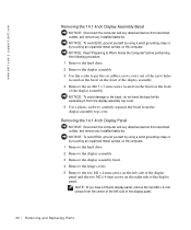
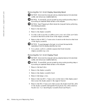
... Remove the display assembly bezel. 4 Remove the hinge covers. 5 Remove the two M2 x 4-mm screws on the computer. www.dell.com | support.dell.com Removing the 14.1-Inch Display Assembly Bezel NOTICE: Disconnect the computer and any attached devices from the display-assembly top cover. NOTICE: ... of the display panel. 30 Removi ng and Replacing Parts Removing the 14.1-Inch Display Panel NOTICE: Disconnect the computer and any installed batteries. NOTICE: Read "Preparing to Work Inside the Computer" before performing the following procedure. 1 Remove the hard drive. 2 Remove the display...
... Remove the display assembly bezel. 4 Remove the hinge covers. 5 Remove the two M2 x 4-mm screws on the computer. www.dell.com | support.dell.com Removing the 14.1-Inch Display Assembly Bezel NOTICE: Disconnect the computer and any attached devices from the display-assembly top cover. NOTICE: ... of the display panel. 30 Removi ng and Replacing Parts Removing the 14.1-Inch Display Panel NOTICE: Disconnect the computer and any installed batteries. NOTICE: Read "Preparing to Work Inside the Computer" before performing the following procedure. 1 Remove the hard drive. 2 Remove the display...
Service Manual
Page 32
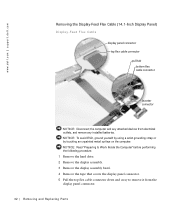
... the display panel connector. 5 Pull the top flex cable connector down and away to remove it from electrical outlets, and remove any installed batteries. www.dell.com | support.dell.com Removing the Display-Feed Flex Cable (14.1-Inch Display Panel) Display-Feed Flex Cable display panel connector top flex cable connector pull tab...
... the display panel connector. 5 Pull the top flex cable connector down and away to remove it from electrical outlets, and remove any installed batteries. www.dell.com | support.dell.com Removing the Display-Feed Flex Cable (14.1-Inch Display Panel) Display-Feed Flex Cable display panel connector top flex cable connector pull tab...
Service Manual
Page 34
... the M2 x 4-mm screw that secures the display-feed flex cable to carefully separate the bezel from electrical outlets, and remove any installed batteries. NOTICE: To avoid ESD, ground yourself by using a wrist grounding strap or by touching an unpainted metal surface on the computer. 1 Remove... bezel. 4 Remove the hinge covers. 5 Remove the four M3 x 3-mm screws on the front of the display assembly. www.dell.com | support.dell.com Removing the 12.1-Inch Display Assembly Bezel NOTICE: Disconnect the computer and any attached devices from electrical outlets, and remove any attached ...
... the M2 x 4-mm screw that secures the display-feed flex cable to carefully separate the bezel from electrical outlets, and remove any installed batteries. NOTICE: To avoid ESD, ground yourself by using a wrist grounding strap or by touching an unpainted metal surface on the computer. 1 Remove... bezel. 4 Remove the hinge covers. 5 Remove the four M3 x 3-mm screws on the front of the display assembly. www.dell.com | support.dell.com Removing the 12.1-Inch Display Assembly Bezel NOTICE: Disconnect the computer and any attached devices from electrical outlets, and remove any attached ...
Service Manual
Page 36
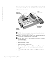
... ESD, ground yourself by using a wrist grounding strap or by touching an unpainted metal surface on the computer. www.dell.com | support.dell.com Removing the Display-Feed Flex Cable (12.1-Inch Display Panel) Display-Feed Flex Cable bottom flex cable connector pull tab... top flex cable connector inverter connector display panel connector NOTICE: Disconnect the computer and any attached devices from electrical outlets, and remove any installed batteries....
... ESD, ground yourself by using a wrist grounding strap or by touching an unpainted metal surface on the computer. www.dell.com | support.dell.com Removing the Display-Feed Flex Cable (12.1-Inch Display Panel) Display-Feed Flex Cable bottom flex cable connector pull tab... top flex cable connector inverter connector display panel connector NOTICE: Disconnect the computer and any attached devices from electrical outlets, and remove any installed batteries....
Service Manual
Page 37
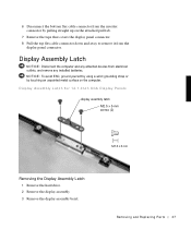
Display Assembly Latch NOTICE: Disconnect the computer and any installed batteries. Removing and Repl aci ng Part s 37 Display Assembly Latch for 14.1-Inch XGA Display Panels display assembly latch M2.5 x 5-mm screws (2) Removing the Display ...
Display Assembly Latch NOTICE: Disconnect the computer and any installed batteries. Removing and Repl aci ng Part s 37 Display Assembly Latch for 14.1-Inch XGA Display Panels display assembly latch M2.5 x 5-mm screws (2) Removing the Display ...
Service Manual
Page 41
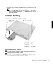
....5 x 12-mm screws (3) M2 x 3-mm screws (2) Removing the Palmrest Assembly NOTICE: Disconnect the computer and any attached devices from electrical outlets, and remove any installed batteries.
....5 x 12-mm screws (3) M2 x 3-mm screws (2) Removing the Palmrest Assembly NOTICE: Disconnect the computer and any attached devices from electrical outlets, and remove any installed batteries.
Service Manual
Page 44
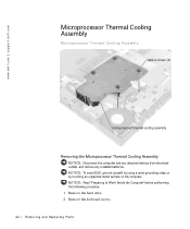
www.dell.com | support.dell.com Microprocessor Thermal Cooling Assembly Microprocessor Thermal Cooling Assembly captive screws (4) microprocessor thermal cooling assembly Removing the Microprocessor Thermal Cooling Assembly NOTICE: Disconnect the computer and any attached devices from electrical outlets, and remove any installed batteries. NOTICE: Read "Preparing to Work Inside the Computer" before performing the following...
www.dell.com | support.dell.com Microprocessor Thermal Cooling Assembly Microprocessor Thermal Cooling Assembly captive screws (4) microprocessor thermal cooling assembly Removing the Microprocessor Thermal Cooling Assembly NOTICE: Disconnect the computer and any attached devices from electrical outlets, and remove any installed batteries. NOTICE: Read "Preparing to Work Inside the Computer" before performing the following...

Service Manual
Page 47
... I ZIF socket type II ZIF socket Removing the Microprocessor Module NOTICE: Disconnect the computer and any attached devices from electrical outlets, and remove any installed batteries. NOTICE: To avoid ESD, ground yourself by using a wrist grounding strap or by touching an unpainted metal surface on the thermal cooling assembly. NOTICE: Read...
... I ZIF socket type II ZIF socket Removing the Microprocessor Module NOTICE: Disconnect the computer and any attached devices from electrical outlets, and remove any installed batteries. NOTICE: To avoid ESD, ground yourself by using a wrist grounding strap or by touching an unpainted metal surface on the thermal cooling assembly. NOTICE: Read...


