Service Manual
Page 5
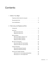
... Work Inside the Computer 10 Recommended Tools 11 Screw Identification 12 2 Removing and Replacing Parts Components 16 Hard Drive 17 Removing the Hard Drive 17 Replacing the Hard Drive 17 Memory Module 18 Removing the Memory Module Cover 18 Removing the Memory Modules 19 Replacing the Memory Modules 20 Mini-PCI Card Assembly 20 Removing the Mini-PCI Card Assembly 22 Replacing the Mini-PCI Card Assembly 22 Keyboard Assembly 23 Removing the Keyboard Assembly 23 Replacing the Keyboard Assembly 25 Removing the Display Assembly 26 Removing...
... Work Inside the Computer 10 Recommended Tools 11 Screw Identification 12 2 Removing and Replacing Parts Components 16 Hard Drive 17 Removing the Hard Drive 17 Replacing the Hard Drive 17 Memory Module 18 Removing the Memory Module Cover 18 Removing the Memory Modules 19 Replacing the Memory Modules 20 Mini-PCI Card Assembly 20 Removing the Mini-PCI Card Assembly 22 Replacing the Mini-PCI Card Assembly 22 Keyboard Assembly 23 Removing the Keyboard Assembly 23 Replacing the Keyboard Assembly 25 Removing the Display Assembly 26 Removing...
Service Manual
Page 6
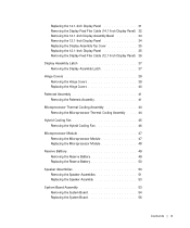
....1-Inch Display Panel 35 Removing the Display-Feed Flex Cable (12.1-Inch Display Panel) 36 Display Assembly Latch 37 Removing the Display Assembly Latch 37 Hinge Covers 39 Removing the Hinge Covers 39 Replacing the Hinge Covers 40 Palmrest Assembly 41 Removing the Palmrest Assembly 41 Microprocessor Thermal Cooling Assembly 44 Removing the Microprocessor Thermal Cooling Assembly . . . . 44 Hybrid Cooling Fan 45 Removing the Hybrid Cooling Fan 46 Microprocessor Module 47 Removing...
....1-Inch Display Panel 35 Removing the Display-Feed Flex Cable (12.1-Inch Display Panel) 36 Display Assembly Latch 37 Removing the Display Assembly Latch 37 Hinge Covers 39 Removing the Hinge Covers 39 Replacing the Hinge Covers 40 Palmrest Assembly 41 Removing the Palmrest Assembly 41 Microprocessor Thermal Cooling Assembly 44 Removing the Microprocessor Thermal Cooling Assembly . . . . 44 Hybrid Cooling Fan 45 Removing the Hybrid Cooling Fan 46 Microprocessor Module 47 Removing...
Service Manual
Page 10
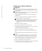
... the Computer NOTICE: Only a certified service technician should perform repairs on a flat work , use . 11 Remove any installed device in progress and close all other external cables from the PC Card slot. 9 Close the display and turn the computer upside down the computer using the computer's operating system, press and hold the power button for 4 seconds. 4 Make sure the computer is not covered by Dell is undocked. 5 Disconnect the computer...
... the Computer NOTICE: Only a certified service technician should perform repairs on a flat work , use . 11 Remove any installed device in progress and close all other external cables from the PC Card slot. 9 Close the display and turn the computer upside down the computer using the computer's operating system, press and hold the power button for 4 seconds. 4 Make sure the computer is not covered by Dell is undocked. 5 Disconnect the computer...
Service Manual
Page 16
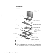
... this manual assumes that a part can be replaced by your system. www.dell.com | support.dell.com Components Exploded View display-assembly top cover keyboard palmrest assembly center control cover left speaker/antenna assembly hard drive main battery thermal cooling assembly hybrid cooling fan system board right speaker/antenna assembly modem and NIC connector covers fan guard modular bay device bottom case assembly memory module cover NOTICE: Only a certified service technician should perform repairs...
... this manual assumes that a part can be replaced by your system. www.dell.com | support.dell.com Components Exploded View display-assembly top cover keyboard palmrest assembly center control cover left speaker/antenna assembly hard drive main battery thermal cooling assembly hybrid cooling fan system board right speaker/antenna assembly modem and NIC connector covers fan guard modular bay device bottom case assembly memory module cover NOTICE: Only a certified service technician should perform repairs...

Service Manual
Page 17
... computer. Replacing the Hard Drive 1 Gently push the hard drive into the drive bay until the drive door is very sensitive to Work Inside the Computer" before performing the following procedure. 1 Remove the M3 x 5-mm screw from the hard drive door. 2 Slide the drive door up until the drive assembly tabs disengage from electrical outlets, and remove any attached devices from the door slots in the...
... computer. Replacing the Hard Drive 1 Gently push the hard drive into the drive bay until the drive door is very sensitive to Work Inside the Computer" before performing the following procedure. 1 Remove the M3 x 5-mm screw from the hard drive door. 2 Slide the drive door up until the drive assembly tabs disengage from electrical outlets, and remove any attached devices from the door slots in the...
Service Manual
Page 18
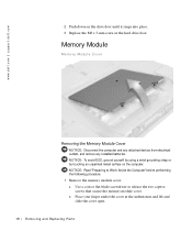
... that secure the memory module cover. www.dell.com | support.dell.com 2 Push down on the computer. Memory Module Memory Module Cover Removing the Memory Module Cover NOTICE: Disconnect the computer and any attached devices from electrical outlets, and remove any installed batteries. b Place your finger under the cover at the indentation and lift and slide the cover open. 18 Removi ng and Replacing Parts NOTICE: To avoid ESD, ground yourself by using a wrist grounding...
... that secure the memory module cover. www.dell.com | support.dell.com 2 Push down on the computer. Memory Module Memory Module Cover Removing the Memory Module Cover NOTICE: Disconnect the computer and any attached devices from electrical outlets, and remove any installed batteries. b Place your finger under the cover at the indentation and lift and slide the cover open. 18 Removi ng and Replacing Parts NOTICE: To avoid ESD, ground yourself by using a wrist grounding...
Service Manual
Page 20
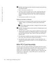
... You must be connected to the system's internal antenna. 20 Removi ng and Replacing Parts A modem, NIC, or modem and NIC combination must remove the optional mini-PCI card assembly before performing the following procedure. 1 Remove the memory module cover. 2 To release a memory module from its socket. Rotate the memory module cover down until it . 4 Insert the tabs on the memory module cover into place. Replacing the Memory Modules 1 If you do...
... You must be connected to the system's internal antenna. 20 Removi ng and Replacing Parts A modem, NIC, or modem and NIC combination must remove the optional mini-PCI card assembly before performing the following procedure. 1 Remove the memory module cover. 2 To release a memory module from its socket. Rotate the memory module cover down until it . 4 Insert the tabs on the memory module cover into place. Replacing the Memory Modules 1 If you do...
Service Manual
Page 22
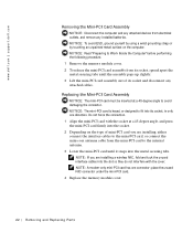
... socket at a 45-degree angle to Work Inside the Computer" before performing the following procedure. 1 Remove the memory module cover. 2 To release the mini-PCI card assembly from electrical outlets, and remove any installed batteries. www.dell.com | support.dell.com Removing the Mini-PCI Card Assembly NOTICE: Disconnect the computer and any attached devices from its socket, spread apart the metal securing tabs until it...
... socket at a 45-degree angle to Work Inside the Computer" before performing the following procedure. 1 Remove the memory module cover. 2 To release the mini-PCI card assembly from electrical outlets, and remove any installed batteries. www.dell.com | support.dell.com Removing the Mini-PCI Card Assembly NOTICE: Disconnect the computer and any attached devices from its socket, spread apart the metal securing tabs until it...

Service Manual
Page 23
... computer and any installed batteries. Removing and Repl aci ng Part s 23 NOTICE: Read "Preparing to replace. NOTICE: To avoid ESD, ground yourself by using a wrist grounding strap or by touching an unpainted metal surface on the keyboard are fragile, easily dislodged, and time-consuming to Work Inside the Computer" before performing the following procedure. 1 Remove the hard drive. 2 Turn the computer over...
... computer and any installed batteries. Removing and Repl aci ng Part s 23 NOTICE: Read "Preparing to replace. NOTICE: To avoid ESD, ground yourself by using a wrist grounding strap or by touching an unpainted metal surface on the keyboard are fragile, easily dislodged, and time-consuming to Work Inside the Computer" before performing the following procedure. 1 Remove the hard drive. 2 Turn the computer over...

Service Manual
Page 47
... for the microprocessor, do not touch) type I ZIF socket type II ZIF socket Removing the Microprocessor Module NOTICE: Disconnect the computer and any attached devices from electrical outlets, and remove any installed batteries. Microprocessor Module Microprocessor Modules NOTICE: Hold the microprocessor down while turning the cam screw to Work Inside the Computer" before performing the following procedure. 1 Remove the hard drive. 2 Remove the keyboard assembly. The oils in...
... for the microprocessor, do not touch) type I ZIF socket type II ZIF socket Removing the Microprocessor Module NOTICE: Disconnect the computer and any attached devices from electrical outlets, and remove any installed batteries. Microprocessor Module Microprocessor Modules NOTICE: Hold the microprocessor down while turning the cam screw to Work Inside the Computer" before performing the following procedure. 1 Remove the hard drive. 2 Remove the keyboard assembly. The oils in...
Service Manual
Page 50
... hard drive. 2 Remove the memory module cover. 3 Disconnect the reserve battery cable from the connector on the EMI shield next to the connector to minimize slack in the cable. 3 Update the BIOS using a flash BIOS update program diskette or CD. Replacing the Reserve Battery 1 Connect the reserve battery cable to the connector on the system board. 2 Position the reserve battery on the system board assembly located next to update or flash the BIOS, see the Dell Portable Computer BIOS Update Guide. b Remove...
... hard drive. 2 Remove the memory module cover. 3 Disconnect the reserve battery cable from the connector on the EMI shield next to the connector to minimize slack in the cable. 3 Update the BIOS using a flash BIOS update program diskette or CD. Replacing the Reserve Battery 1 Connect the reserve battery cable to the connector on the system board. 2 Position the reserve battery on the system board assembly located next to update or flash the BIOS, see the Dell Portable Computer BIOS Update Guide. b Remove...
Service Manual
Page 56
..., the display assembly, the keyboard assembly, and the hard drive. 6 Replace the modular bay devices and any PC Cards or plastic blanks in the PC Card slot. 7 Insert the diskette or CD that accompanied the replacement system board assembly into the appropriate drive, and turn on the screen. Replacing the System Board 1 Install the microprocessor on the right side of the bottom case assembly. a Insert the external microphone and...
..., the display assembly, the keyboard assembly, and the hard drive. 6 Replace the modular bay devices and any PC Cards or plastic blanks in the PC Card slot. 7 Insert the diskette or CD that accompanied the replacement system board assembly into the appropriate drive, and turn on the screen. Replacing the System Board 1 Install the microprocessor on the right side of the bottom case assembly. a Insert the external microphone and...
System Information Guide
Page 4
... describe changes to your computer or software. support.dell.com Dell Latitude System Information 1-1 NOTE: The Getting Started placemat is not available in your operat- ing system software from Dell. • Documentation included with any other Dell documents that you need to configure and install these updates before consulting any options you ordered your Dell computer. (Rev. 11/3/98) FILE LOCATION: D:\Eri_DProject\Dell\Temp\413CU0s\413CUeb0.fm Dell™ Latitude™...
... describe changes to your computer or software. support.dell.com Dell Latitude System Information 1-1 NOTE: The Getting Started placemat is not available in your operat- ing system software from Dell. • Documentation included with any other Dell documents that you need to configure and install these updates before consulting any options you ordered your Dell computer. (Rev. 11/3/98) FILE LOCATION: D:\Eri_DProject\Dell\Temp\413CU0s\413CUeb0.fm Dell™ Latitude™...
System Information Guide
Page 5
... temperatures and may result in your hard-disk drive as well as other troubleshooting information from potential damage and to help prevent electric shock, plug the AC adapter and peripheral power cables into the extension cable does not exceed the ampere rating of the extension cable. 1-2 Dell Latitude System Information These cables are approved for use adapter plugs or remove the grounding prong from burns...
... temperatures and may result in your hard-disk drive as well as other troubleshooting information from potential damage and to help prevent electric shock, plug the AC adapter and peripheral power cables into the extension cable does not exceed the ampere rating of the extension cable. 1-2 Dell Latitude System Information These cables are approved for use adapter plugs or remove the grounding prong from burns...
System Information Guide
Page 6
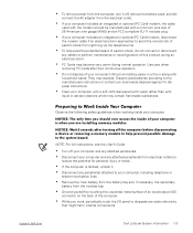
... normal operation. Use care when removing PC Cards after turning off , remove the battery pack, and dis- NOTICE: The only time you are installing memory modules. NOTICE: Wait 5 seconds after their continuous operation. • Do not dispose of your computer is docked, undock it off the computer before disconnecting a device or removing a memory module to help avoid the potential hazard of electric shock, do not connect...
... normal operation. Use care when removing PC Cards after turning off , remove the battery pack, and dis- NOTICE: The only time you are installing memory modules. NOTICE: Wait 5 seconds after their continuous operation. • Do not dispose of your computer is docked, undock it off the computer before disconnecting a device or removing a memory module to help avoid the potential hazard of electric shock, do not connect...
System Information Guide
Page 8
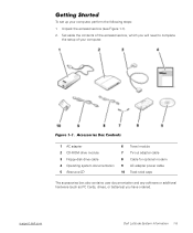
...-ROM drive module 3 Floppy-disk drive cable 4 Operating system documentation 5 ResourceCD 6 Travel module 7 TV-out adapter cable 8 Cable for optional modem 9 AC adapter power cable 10 Track stick caps The accessories box also contains user documentation and any software or additional hardware (such as PC Cards, drives, or batteries) you will need to complete the setup of the accessories box, which you have ordered. (Rev. 11/3/98) FILE LOCATION: D:\Eri_DProject\Dell\Temp\413CU0s\413CUeb0.fm Getting Started...
...-ROM drive module 3 Floppy-disk drive cable 4 Operating system documentation 5 ResourceCD 6 Travel module 7 TV-out adapter cable 8 Cable for optional modem 9 AC adapter power cable 10 Track stick caps The accessories box also contains user documentation and any software or additional hardware (such as PC Cards, drives, or batteries) you will need to complete the setup of the accessories box, which you have ordered. (Rev. 11/3/98) FILE LOCATION: D:\Eri_DProject\Dell\Temp\413CU0s\413CUeb0.fm Getting Started...
System Information Guide
Page 11
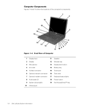
...\413CU0s\413CUeb0.fm Computer Components Figures 1-4 and 1-5 show the locations of Computer 1 Display latch 11 Speaker 2 Display 12 Modular bay 3 Microphone 13 Display latch button 4 Air outlet 14 Battery bay 5 S-Video connector 15 Touch pad 6 Optional network connector 16 Track stick 7 Optional modem connector 17 Keyboard status lights 8 Audio jacks (2) 18 Power button 9 System status lights 19 Dell AccessDirect™ key 10 Infrared port 1-8 Dell Latitude System Information Front View of the computer's components. Figure 1-4.
...\413CU0s\413CUeb0.fm Computer Components Figures 1-4 and 1-5 show the locations of Computer 1 Display latch 11 Speaker 2 Display 12 Modular bay 3 Microphone 13 Display latch button 4 Air outlet 14 Battery bay 5 S-Video connector 15 Touch pad 6 Optional network connector 16 Track stick 7 Optional modem connector 17 Keyboard status lights 8 Audio jacks (2) 18 Power button 9 System status lights 19 Dell AccessDirect™ key 10 Infrared port 1-8 Dell Latitude System Information Front View of the computer's components. Figure 1-4.
System Information Guide
Page 13
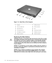
... connected to use the battery in CS or CSx, and do not replace a battery while the computer is turned on unless the computer is installed. You can use your computer. NOTICE: Only use a battery from Dell. Back View of the Computer 1 Speaker 2 Security cable slot 3 Hard-disk drive 4 PC Card slots (2) 5 AC adapter connector 6 Video connector 7 USB connector 8 PS/2 connector 9 Fan 10 Docking connector 11 Parallel connector 12 Serial connector Replacing the Main Battery CAUTION: Using...
... connected to use the battery in CS or CSx, and do not replace a battery while the computer is turned on unless the computer is installed. You can use your computer. NOTICE: Only use a battery from Dell. Back View of the Computer 1 Speaker 2 Security cable slot 3 Hard-disk drive 4 PC Card slots (2) 5 AC adapter connector 6 Video connector 7 USB connector 8 PS/2 connector 9 Fan 10 Docking connector 11 Parallel connector 12 Serial connector Replacing the Main Battery CAUTION: Using...
System Information Guide
Page 14
.... 2. support.dell.com Dell Latitude System Information 1-11 Save your User's Guide. 1. Place the computer in the battery bay, perform the following steps. (Rev. 11/3/98) FILE LOCATION: D:\Eri_DProject\Dell\Temp\413CU0s\413CUeb0.fm Before installing a new battery, check the battery's charge, by pressing (or on a French keyboard). To replace a battery in suspend mode by pressing the battery test button. When the green power indicator turns off, continue. • For Windows 2000, use suspend-to replace...
.... 2. support.dell.com Dell Latitude System Information 1-11 Save your User's Guide. 1. Place the computer in the battery bay, perform the following steps. (Rev. 11/3/98) FILE LOCATION: D:\Eri_DProject\Dell\Temp\413CU0s\413CUeb0.fm Before installing a new battery, check the battery's charge, by pressing (or on a French keyboard). To replace a battery in suspend mode by pressing the battery test button. When the green power indicator turns off, continue. • For Windows 2000, use suspend-to replace...
System Information Guide
Page 18
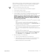
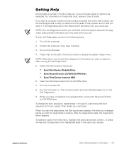
... the following boot sequence: • Boot First Device: Diskette Drive • Boot Second Device: CD/DVD/CD-RW Drive • Boot Third Device: Internal HDD 6. Turn on . The computer starts and automatically begins to run the Dell Diagnostics. 9. Then restart your needs. support.dell.com Dell Latitude System Information 1-15 NOTE: Write down your current boot sequence in the option you if your computer does not perform as expected. To change the boot sequence...
... the following boot sequence: • Boot First Device: Diskette Drive • Boot Second Device: CD/DVD/CD-RW Drive • Boot Third Device: Internal HDD 6. Turn on . The computer starts and automatically begins to run the Dell Diagnostics. 9. Then restart your needs. support.dell.com Dell Latitude System Information 1-15 NOTE: Write down your current boot sequence in the option you if your computer does not perform as expected. To change the boot sequence...


