Service Manual
Page 4
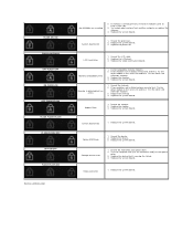
...slot. 3. Memory is causing the failure. 4. Reseat the memory. 2. Replace the modem. 3. Replace the system board. 3. Test the other slot with just the hard drive and just the optical drive. 3. Replace the memory 4. Reseat the LCD cable. 2. Replace the device. 3. If memory is already present, reseat the module(s) ...one at time in the same slot and test. Reseat the hard drive and optical drive. 2. Replace the memory. 4. FLASH-ON-ON FLASH-ON-FLASH OFF-FLASH-OFF ON-FLASH-ON OFF-FLASH-FLASH FLASH-FLASH...
...slot. 3. Memory is causing the failure. 4. Reseat the memory. 2. Replace the modem. 3. Replace the system board. 3. Test the other slot with just the hard drive and just the optical drive. 3. Replace the memory 4. Reseat the LCD cable. 2. Replace the device. 3. If memory is already present, reseat the module(s) ...one at time in the same slot and test. Reseat the hard drive and optical drive. 2. Replace the memory. 4. FLASH-ON-ON FLASH-ON-FLASH OFF-FLASH-OFF ON-FLASH-ON OFF-FLASH-FLASH FLASH-FLASH...
Service Manual
Page 5
Back to Contents Page Adding and Replacing Parts Dell™ Latitude™ 2100 Service Manual Battery Access Panel Coin-Cell Battery Heat Sink Hard Drive Bracket Display Bezel Display Panel Display Brackets DC Power Cable Hinge Cover Keyboard Memory WLAN Card Hard Drive Display Assembly Display LED Board Display Cable Display Hinges System Board Internal Card With Bluetooth® Wireless Technology Back to Contents Page
Back to Contents Page Adding and Replacing Parts Dell™ Latitude™ 2100 Service Manual Battery Access Panel Coin-Cell Battery Heat Sink Hard Drive Bracket Display Bezel Display Panel Display Brackets DC Power Cable Hinge Cover Keyboard Memory WLAN Card Hard Drive Display Assembly Display LED Board Display Cable Display Hinges System Board Internal Card With Bluetooth® Wireless Technology Back to Contents Page

Service Manual
Page 36
...replaced or--if purchased separately--installed by performing the removal procedure in this document assumes that both connectors are disconnecting this document. Hold a card by its edges or by your work surface is connected to a docking device (docked) such as the metal at www.dell... the computer. 5. Remove the main battery (see Removing the Hard Drive). Press the power button to dissipate static electricity, which could ... Remove any connector pins. Working on Your Computer Dell™ Latitude™ 2100 Service Manual Before Working Inside Your Computer Recommended Tools...
...replaced or--if purchased separately--installed by performing the removal procedure in this document assumes that both connectors are disconnecting this document. Hold a card by its edges or by your work surface is connected to a docking device (docked) such as the metal at www.dell... the computer. 5. Remove the main battery (see Removing the Hard Drive). Press the power button to dissipate static electricity, which could ... Remove any connector pins. Working on Your Computer Dell™ Latitude™ 2100 Service Manual Before Working Inside Your Computer Recommended Tools...


