
Setup Guide
Page 7
...carpets or rugs, while it is powered on the computer may cause it to place your Dell Inspiron laptop. CAUTION: Placing or stacking heavy or sharp objects on . You should never place your Dell computer in the air vents. Before Setting Up Your Computer When positioning your laptop may ...ensure that you allow dust to the computer. 5 Restricting the airflow can damage the computer, deteriorate the computer performance, or cause a fire. Fan noise is powered on fabric surfaces, such as a cabinet or drawer when it is normal and does not indicate a problem with the...
...carpets or rugs, while it is powered on the computer may cause it to place your Dell Inspiron laptop. CAUTION: Placing or stacking heavy or sharp objects on . You should never place your Dell computer in the air vents. Before Setting Up Your Computer When positioning your laptop may ...ensure that you allow dust to the computer. 5 Restricting the airflow can damage the computer, deteriorate the computer performance, or cause a fire. Fan noise is powered on fabric surfaces, such as a cabinet or drawer when it is normal and does not indicate a problem with the...
Setup Guide
Page 7
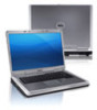
...computer, deteriorate the computer performance, or cause a fire. Restricting airflow around your computer, ensure that you allow dust to place your Dell computer in a low-airflow environment, such as a cabinet or drawer when it is powered on the computer may cause it is normal...inches) at the back of the computer and a minimum of 5.1 cm (2 inches) on the fan when the computer gets hot. You should never place your Dell Inspiron laptop. INSPIRON Setting Up Your Inspiron Laptop This section provides information about setting up your computer in an enclosed space, such as a ...
...computer, deteriorate the computer performance, or cause a fire. Restricting airflow around your computer, ensure that you allow dust to place your Dell computer in a low-airflow environment, such as a cabinet or drawer when it is powered on the computer may cause it is normal...inches) at the back of the computer and a minimum of 5.1 cm (2 inches) on the fan when the computer gets hot. You should never place your Dell Inspiron laptop. INSPIRON Setting Up Your Inspiron Laptop This section provides information about setting up your computer in an enclosed space, such as a ...
Service Manual
Page 5
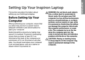
11 Wireless Mini-Card(s 45 Removing the Mini-Card(s 45 Replacing the Mini-Card(s 47 12 Thermal Fan 49 Removing the Thermal Fan 49 Replacing the Thermal Fan 50 13 Display 53 Display Assembly 53 Removing the Display Assembly 53 Replacing the Display Assembly 56 Display Bezel 57 Removing the Display Bezel 57 ...
11 Wireless Mini-Card(s 45 Removing the Mini-Card(s 45 Replacing the Mini-Card(s 47 12 Thermal Fan 49 Removing the Thermal Fan 49 Replacing the Thermal Fan 50 13 Display 53 Display Assembly 53 Removing the Display Assembly 53 Replacing the Display Assembly 56 Display Bezel 57 Removing the Display Bezel 57 ...

Service Manual
Page 49
..."Removing the Palm-Rest Assembly" on page 31). 5 Disconnect the display cable from the connector on the system board. 6 Disconnect the thermal fan cable from the connector on the system board. 7 Remove the screw that shipped with your computer. CAUTION: To help prevent damage to servicing that... is not authorized by Dell is not covered by periodically touching an unpainted metal surface (such as a connector on your computer. Damage due to the system board, remove...
..."Removing the Palm-Rest Assembly" on page 31). 5 Disconnect the display cable from the connector on the system board. 6 Disconnect the thermal fan cable from the connector on the system board. 7 Remove the screw that shipped with your computer. CAUTION: To help prevent damage to servicing that... is not authorized by Dell is not covered by periodically touching an unpainted metal surface (such as a connector on your computer. Damage due to the system board, remove...

Service Manual
Page 50
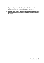
4 3 2 1 1 screw 2 thermal fan 3 thermal fan connector 4 display cable Replacing the Thermal Fan 1 Follow the instructions in "Before You Begin" on page 9. 2 Place the thermal fan on the computer base and replace the screw. 3 Connect the thermal fan cable to the connector on the system board. 4 Connect the display cable to the connector on the system board. 5 Replace the palm-rest assembly (see "Replacing the Palm-Rest Assembly" on page 35). 50 Thermal Fan
4 3 2 1 1 screw 2 thermal fan 3 thermal fan connector 4 display cable Replacing the Thermal Fan 1 Follow the instructions in "Before You Begin" on page 9. 2 Place the thermal fan on the computer base and replace the screw. 3 Connect the thermal fan cable to the connector on the system board. 4 Connect the display cable to the connector on the system board. 5 Replace the palm-rest assembly (see "Replacing the Palm-Rest Assembly" on page 35). 50 Thermal Fan
Service Manual
Page 51
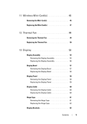
Thermal Fan 51 CAUTION: Before turning on page 16). 6 Replace the keyboard (see "Replacing the Keyboard" on page 29). 7 Replace the battery (see "Replacing the Battery" on the computer, replace all screws and ensure that no stray screws remain inside the computer. Failure to do so may result in damage to the computer.
Thermal Fan 51 CAUTION: Before turning on page 16). 6 Replace the keyboard (see "Replacing the Keyboard" on page 29). 7 Replace the battery (see "Replacing the Battery" on the computer, replace all screws and ensure that no stray screws remain inside the computer. Failure to do so may result in damage to the computer.

Service Manual
Page 52
52 Thermal Fan
52 Thermal Fan

Service Manual
Page 78
1 1 AC-adapter connector cable 8 Remove the keyboard (see "Removing the Keyboard" on page 27). 9 Remove the palm-rest assembly (see "Removing the Palm-Rest Assembly" on page 31). 10 Remove the thermal fan (see "Removing the Thermal Fan" on page 49). 11 Loosen the display cable grounding screw. 12 Disconnect the display cable and speakers cable from the connectors on the system board. 13 Remove the five screws that secure the system board to the computer base. 78 System Board
1 1 AC-adapter connector cable 8 Remove the keyboard (see "Removing the Keyboard" on page 27). 9 Remove the palm-rest assembly (see "Removing the Palm-Rest Assembly" on page 31). 10 Remove the thermal fan (see "Removing the Thermal Fan" on page 49). 11 Loosen the display cable grounding screw. 12 Disconnect the display cable and speakers cable from the connectors on the system board. 13 Remove the five screws that secure the system board to the computer base. 78 System Board
Service Manual
Page 81
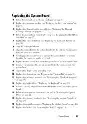
... display cable and speakers cable to the connectors on the system board. 11 Tighten the display cable grounding screw. 12 Replace the thermal fan (see "Replacing the Thermal Fan" on page 50). 13 Replace the palm-rest assembly (see "Replacing the Palm-Rest Assembly" on page 35). 14 Replace the keyboard (see...
... display cable and speakers cable to the connectors on the system board. 11 Tighten the display cable grounding screw. 12 Replace the thermal fan (see "Replacing the Thermal Fan" on page 50). 13 Replace the palm-rest assembly (see "Replacing the Palm-Rest Assembly" on page 35). 14 Replace the keyboard (see...

Service Manual
Page 5
11 Wireless Mini-Card(s 45 Removing the Mini-Card(s 45 Replacing the Mini-Card(s 47 12 Thermal Fan 49 Removing the Thermal Fan 49 Replacing the Thermal Fan 50 13 Display 53 Display Assembly 53 Removing the Display Assembly 53 Replacing the Display Assembly 56 Display Bezel 57 Removing the Display Bezel 57 ...
11 Wireless Mini-Card(s 45 Removing the Mini-Card(s 45 Replacing the Mini-Card(s 47 12 Thermal Fan 49 Removing the Thermal Fan 49 Replacing the Thermal Fan 50 13 Display 53 Display Assembly 53 Removing the Display Assembly 53 Replacing the Display Assembly 56 Display Bezel 57 Removing the Display Bezel 57 ...

Service Manual
Page 49
...5 Disconnect the display cable from the connector on the system board. 6 Disconnect the thermal fan cable from the connector on the system board. 7 Remove the screw that is not authorized by Dell is not covered by periodically touching an unpainted metal surface (such as a connector on your ...15) before working inside the computer. Damage due to servicing that secures the thermal fan to the system board, remove the main battery (see the Regulatory Compliance Homepage at dell.com/regulatory_compliance. Thermal Fan 49 CAUTION: To help prevent damage to the computer base. 8 Lift the ...
...5 Disconnect the display cable from the connector on the system board. 6 Disconnect the thermal fan cable from the connector on the system board. 7 Remove the screw that is not authorized by Dell is not covered by periodically touching an unpainted metal surface (such as a connector on your ...15) before working inside the computer. Damage due to servicing that secures the thermal fan to the system board, remove the main battery (see the Regulatory Compliance Homepage at dell.com/regulatory_compliance. Thermal Fan 49 CAUTION: To help prevent damage to the computer base. 8 Lift the ...

Service Manual
Page 50
4 3 2 1 1 screw 2 thermal fan 3 thermal fan connector 4 display cable Replacing the Thermal Fan 1 Follow the instructions in "Before You Begin" on page 9. 2 Place the thermal fan on the computer base and replace the screw. 3 Connect the thermal fan cable to the connector on the system board. 4 Connect the display cable to the connector on the system board. 5 Replace the palm-rest assembly (see "Replacing the Palm-Rest Assembly" on page 35). 50 Thermal Fan
4 3 2 1 1 screw 2 thermal fan 3 thermal fan connector 4 display cable Replacing the Thermal Fan 1 Follow the instructions in "Before You Begin" on page 9. 2 Place the thermal fan on the computer base and replace the screw. 3 Connect the thermal fan cable to the connector on the system board. 4 Connect the display cable to the connector on the system board. 5 Replace the palm-rest assembly (see "Replacing the Palm-Rest Assembly" on page 35). 50 Thermal Fan

Service Manual
Page 51
CAUTION: Before turning on page 16). Thermal Fan 51 6 Replace the keyboard (see "Replacing the Keyboard" on page 29). 7 Replace the battery (see "Replacing the Battery" on the computer, replace all screws and ensure that no stray screws remain inside the computer. Failure to do so may result in damage to the computer.
CAUTION: Before turning on page 16). Thermal Fan 51 6 Replace the keyboard (see "Replacing the Keyboard" on page 29). 7 Replace the battery (see "Replacing the Battery" on the computer, replace all screws and ensure that no stray screws remain inside the computer. Failure to do so may result in damage to the computer.

Service Manual
Page 52
52 Thermal Fan
52 Thermal Fan

Service Manual
Page 78
1 1 AC-adapter connector cable 8 Remove the keyboard (see "Removing the Keyboard" on page 27). 9 Remove the palm-rest assembly (see "Removing the Palm-Rest Assembly" on page 31). 10 Remove the thermal fan (see "Removing the Thermal Fan" on page 49). 11 Loosen the display cable grounding screw. 12 Disconnect the display cable and speakers cable from the connectors on the system board. 13 Remove the five screws that secure the system board to the computer base. 78 System Board
1 1 AC-adapter connector cable 8 Remove the keyboard (see "Removing the Keyboard" on page 27). 9 Remove the palm-rest assembly (see "Removing the Palm-Rest Assembly" on page 31). 10 Remove the thermal fan (see "Removing the Thermal Fan" on page 49). 11 Loosen the display cable grounding screw. 12 Disconnect the display cable and speakers cable from the connectors on the system board. 13 Remove the five screws that secure the system board to the computer base. 78 System Board

Service Manual
Page 81
... display cable and speakers cable to the connectors on the system board. 11 Tighten the display cable grounding screw. 12 Replace the thermal fan (see "Replacing the Thermal Fan" on page 50). 13 Replace the palm-rest assembly (see "Replacing the Palm-Rest Assembly" on page 35). 14 Replace the keyboard (see...
... display cable and speakers cable to the connectors on the system board. 11 Tighten the display cable grounding screw. 12 Replace the thermal fan (see "Replacing the Thermal Fan" on page 50). 13 Replace the palm-rest assembly (see "Replacing the Palm-Rest Assembly" on page 35). 14 Replace the keyboard (see...


