Setup Guide
Page 5
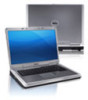
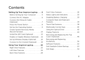
...Optional 12 Enable or Disable Wireless (Optional 14 Set Up Wireless Display (Optional 16 Connect to the Internet (Optional 18 Using Your Inspiron Laptop 22 Right View Features 22 Left View Features 24 Back View Features 28 Front View Features 30 Status Lights and ... Disabling Battery Charging 33 Computer Base and Keyboard Features 34 Touch Pad Gestures 38 Multimedia Control Keys 40 Using the Optical Drive 42 Display Features 44 Removing and Replacing the Top Cover (Optional 46 Removing and Replacing the Battery 50 Software Features 52 Dell DataSafe Online Backup 53...
...Optional 12 Enable or Disable Wireless (Optional 14 Set Up Wireless Display (Optional 16 Connect to the Internet (Optional 18 Using Your Inspiron Laptop 22 Right View Features 22 Left View Features 24 Back View Features 28 Front View Features 30 Status Lights and ... Disabling Battery Charging 33 Computer Base and Keyboard Features 34 Touch Pad Gestures 38 Multimedia Control Keys 40 Using the Optical Drive 42 Display Features 44 Removing and Replacing the Top Cover (Optional 46 Removing and Replacing the Battery 50 Software Features 52 Dell DataSafe Online Backup 53...
Setup Guide
Page 5
...Optional 12 Enable or Disable Wireless (Optional 14 Set Up Wireless Display (Optional 16 Connect to the Internet (Optional 18 Using Your Inspiron Laptop 22 Right View Features 22 Left View Features 24 Back View Features 28 Front View Features 30 Status Lights and ... Disabling Battery Charging 33 Computer Base and Keyboard Features 34 Touch Pad Gestures 38 Multimedia Control Keys 40 Using the Optical Drive 42 Display Features 44 Removing and Replacing the Top Cover (Optional 46 Removing and Replacing the Battery 50 Software Features 52 Dell DataSafe Online Backup 53...
...Optional 12 Enable or Disable Wireless (Optional 14 Set Up Wireless Display (Optional 16 Connect to the Internet (Optional 18 Using Your Inspiron Laptop 22 Right View Features 22 Left View Features 24 Back View Features 28 Front View Features 30 Status Lights and ... Disabling Battery Charging 33 Computer Base and Keyboard Features 34 Touch Pad Gestures 38 Multimedia Control Keys 40 Using the Optical Drive 42 Display Features 44 Removing and Replacing the Top Cover (Optional 46 Removing and Replacing the Battery 50 Software Features 52 Dell DataSafe Online Backup 53...

Service Manual
Page 4
Replacing the Optical Drive 21 6 Memory Module(s 23 Removing the Memory Module(s 23 Replacing the Memory Module(s 24 7 Keyboard 27 Removing the Keyboard 27 Replacing the Keyboard 29 8 Palm-Rest Assembly 31 Removing the Palm-Rest Assembly 31 Replacing the Palm-Rest Assembly 34 9 Hot-Key Board 37 Removing the Hot-Key Board 37 Replacing the Hot-Key Board 38 10 Power Button Board 41 Removing the Power Button Board 41 Replacing the Power Button Board 42 4 Contents
Replacing the Optical Drive 21 6 Memory Module(s 23 Removing the Memory Module(s 23 Replacing the Memory Module(s 24 7 Keyboard 27 Removing the Keyboard 27 Replacing the Keyboard 29 8 Palm-Rest Assembly 31 Removing the Palm-Rest Assembly 31 Replacing the Palm-Rest Assembly 34 9 Hot-Key Board 37 Removing the Hot-Key Board 37 Replacing the Hot-Key Board 38 10 Power Button Board 41 Removing the Power Button Board 41 Replacing the Power Button Board 42 4 Contents
Service Manual
Page 27
... battery (see the Regulatory Compliance Homepage at dell.com/regulatory_compliance. Damage due to replace. CAUTION: Do not slide the plastic scribe under the keyboard tabs to remove the keyboard as it may cause permanent damage to the keyboard tabs. 4 Slide a plastic scribe between the slots on the keyboard and release the tabs on the palm rest...
... battery (see the Regulatory Compliance Homepage at dell.com/regulatory_compliance. Damage due to replace. CAUTION: Do not slide the plastic scribe under the keyboard tabs to remove the keyboard as it may cause permanent damage to the keyboard tabs. 4 Slide a plastic scribe between the slots on the keyboard and release the tabs on the palm rest...
Service Manual
Page 29
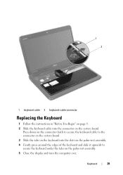
1 2 1 keyboard cable 2 keyboard-cable connector Replacing the Keyboard 1 Follow the instructions in "Before You Begin" on page 9. 2 Slide the keyboard cable into the slots on the palm-rest assembly. 4 Gently press around the edges of the keyboard and slide it upwards to the connector on the system board. 3 Slide the tabs on the keyboard into the connector on the palm-rest assembly. 5 Close the display and turn the computer over. Press down on the connector latch to secure the keyboard cable to secure the keyboard under the tabs on the system board. Keyboard 29
1 2 1 keyboard cable 2 keyboard-cable connector Replacing the Keyboard 1 Follow the instructions in "Before You Begin" on page 9. 2 Slide the keyboard cable into the slots on the palm-rest assembly. 4 Gently press around the edges of the keyboard and slide it upwards to the connector on the system board. 3 Slide the tabs on the keyboard into the connector on the palm-rest assembly. 5 Close the display and turn the computer over. Press down on the connector latch to secure the keyboard cable to secure the keyboard under the tabs on the system board. Keyboard 29
Service Manual
Page 30
6 Replace the battery (see "Replacing the Battery" on page 16). 30 Keyboard
6 Replace the battery (see "Replacing the Battery" on page 16). 30 Keyboard

Service Manual
Page 35
... on the system board and press down on the connector latches to secure them. 6 Replace the five screws on the palm-rest assembly. 7 Replace the keyboard (see "Replacing the Battery" on the computer, replace all screws and ensure that no stray screws remain inside the computer. Palm-Rest Assembly ...and gently snap the palm-rest assembly in "Replacing the Optical Drive" on page 21. 10 Replace the module cover (see "Replacing the Module Cover" on page 18). 11 Replace the battery (see "Replacing the Keyboard" on page 29). 8 Turn the computer over and replace the ten screws at the bottom of the ...
... on the system board and press down on the connector latches to secure them. 6 Replace the five screws on the palm-rest assembly. 7 Replace the keyboard (see "Replacing the Battery" on the computer, replace all screws and ensure that no stray screws remain inside the computer. Palm-Rest Assembly ...and gently snap the palm-rest assembly in "Replacing the Optical Drive" on page 21. 10 Replace the module cover (see "Replacing the Module Cover" on page 18). 11 Replace the battery (see "Replacing the Keyboard" on page 29). 8 Turn the computer over and replace the ten screws at the bottom of the ...
Service Manual
Page 38
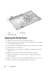
..." on the palm- 1 2 3 1 screw 2 hot-key board 3 hot-key board cable Replacing the Hot-Key Board 1 Follow the instructions in "Replacing the Optical Drive" on page 21. 8 Replace the module cover (see "Replacing the Module Cover" on page 18). 9 Replace the battery (see "Replacing the Keyboard" on page 29). 7 Follow the instructions from step 4 to step 5 in...
..." on the palm- 1 2 3 1 screw 2 hot-key board 3 hot-key board cable Replacing the Hot-Key Board 1 Follow the instructions in "Replacing the Optical Drive" on page 21. 8 Replace the module cover (see "Replacing the Module Cover" on page 18). 9 Replace the battery (see "Replacing the Keyboard" on page 29). 7 Follow the instructions from step 4 to step 5 in...
Service Manual
Page 42
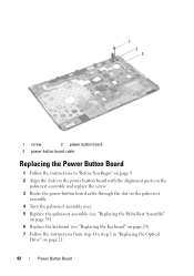
... through the slot on the palm-rest assembly. 4 Turn the palm-rest assembly over. 5 Replace the palm-rest assembly (see "Replacing the Palm-Rest Assembly" on page 35). 6 Replace the keyboard (see "Replacing the Keyboard" on page 29). 7 Follow the instructions from step 4 to step 5 in "Replacing the Optical Drive" on page 21. 42 Power Button Board
... through the slot on the palm-rest assembly. 4 Turn the palm-rest assembly over. 5 Replace the palm-rest assembly (see "Replacing the Palm-Rest Assembly" on page 35). 6 Replace the keyboard (see "Replacing the Keyboard" on page 29). 7 Follow the instructions from step 4 to step 5 in "Replacing the Optical Drive" on page 21. 42 Power Button Board
Service Manual
Page 48
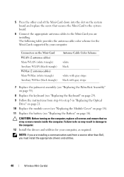
5 Press the other than Dell, you are installing a communication card from step 4 to step 5 in damage to the Mini-Card you must install the appropriate drivers and utilities. 48 Wireless ...) Auxiliary WiMax (black triangle) Antenna Cable Color Scheme white black white with gray stripe black with gray stripe 7 Replace the palm-rest assembly (see "Replacing the Palm-Rest Assembly" on page 35). 8 Replace the keyboard (see "Replacing the Keyboard" on page 29). 9 Follow the instructions from a source other end of the Mini-Card down into the...
5 Press the other than Dell, you are installing a communication card from step 4 to step 5 in damage to the Mini-Card you must install the appropriate drivers and utilities. 48 Wireless ...) Auxiliary WiMax (black triangle) Antenna Cable Color Scheme white black white with gray stripe black with gray stripe 7 Replace the palm-rest assembly (see "Replacing the Palm-Rest Assembly" on page 35). 8 Replace the keyboard (see "Replacing the Keyboard" on page 29). 9 Follow the instructions from a source other end of the Mini-Card down into the...
Service Manual
Page 51
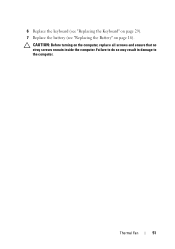
Failure to do so may result in damage to the computer. 6 Replace the keyboard (see "Replacing the Keyboard" on page 29). 7 Replace the battery (see "Replacing the Battery" on the computer, replace all screws and ensure that no stray screws remain inside the computer. CAUTION: Before turning on page 16). Thermal Fan 51
Failure to do so may result in damage to the computer. 6 Replace the keyboard (see "Replacing the Keyboard" on page 29). 7 Replace the battery (see "Replacing the Battery" on the computer, replace all screws and ensure that no stray screws remain inside the computer. CAUTION: Before turning on page 16). Thermal Fan 51
Service Manual
Page 57
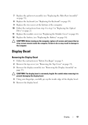
...Begin" on page 9. 2 Remove the top cover (see "Removing the Top Cover" on page 13). 3 Remove the display assembly (see "Replacing the Battery" on page 16). Be careful when removing it to prevent damaging the display bezel. 4 Using your fingertips, carefully pry up the ... Follow the instructions from step 4 to step 5 in damage to the computer. 7 Replace the palm-rest assembly (see "Replacing the Palm-Rest Assembly" on page 35). 8 Replace the keyboard (see "Replacing the Keyboard" on page 29). 9 Replace the two screws at the bottom of the display bezel. 5 Remove the display bezel....
...Begin" on page 9. 2 Remove the top cover (see "Removing the Top Cover" on page 13). 3 Remove the display assembly (see "Replacing the Battery" on page 16). Be careful when removing it to prevent damaging the display bezel. 4 Using your fingertips, carefully pry up the ... Follow the instructions from step 4 to step 5 in damage to the computer. 7 Replace the palm-rest assembly (see "Replacing the Palm-Rest Assembly" on page 35). 8 Replace the keyboard (see "Replacing the Keyboard" on page 29). 9 Replace the two screws at the bottom of the display bezel. 5 Remove the display bezel....
Service Manual
Page 67
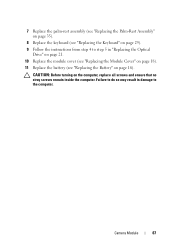
Camera Module 67 Failure to do so may result in damage to step 5 in "Replacing the Optical Drive" on page 21. 10 Replace the module cover (see "Replacing the Module Cover" on page 18). 11 Replace the battery (see "Replacing the Keyboard" on page 29). 9 Follow the instructions from step 4 to the computer. 7 Replace the palm-rest assembly (see "Replacing the Palm-Rest Assembly" on page 35). 8 Replace the keyboard (see "Replacing the Battery" on page 16). CAUTION: Before turning on the computer, replace all screws and ensure that no stray screws remain inside the computer.
Camera Module 67 Failure to do so may result in damage to step 5 in "Replacing the Optical Drive" on page 21. 10 Replace the module cover (see "Replacing the Module Cover" on page 18). 11 Replace the battery (see "Replacing the Keyboard" on page 29). 9 Follow the instructions from step 4 to the computer. 7 Replace the palm-rest assembly (see "Replacing the Palm-Rest Assembly" on page 35). 8 Replace the keyboard (see "Replacing the Battery" on page 16). CAUTION: Before turning on the computer, replace all screws and ensure that no stray screws remain inside the computer.
Service Manual
Page 71
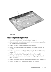
... base and snap the hinge cover into place. 3 Replace the two screws at the bottom of the computer. 4 Replace the display assembly (see "Replacing the Display Assembly" on page 56). 5 Replace the palm-rest assembly (see "Replacing the Palm-Rest Assembly" on page 35). 6 Replace the keyboard (see "Replacing the Keyboard" on page 29). 7 Follow the instructions from step...
... base and snap the hinge cover into place. 3 Replace the two screws at the bottom of the computer. 4 Replace the display assembly (see "Replacing the Display Assembly" on page 56). 5 Replace the palm-rest assembly (see "Replacing the Palm-Rest Assembly" on page 35). 6 Replace the keyboard (see "Replacing the Keyboard" on page 29). 7 Follow the instructions from step...

Service Manual
Page 74
... the VGA connector board to the computer base. 5 Replace the hinge cover (see "Replacing the Hinge Cover" on page 71). 6 Replace the display assembly (see "Replacing the Display Assembly" on page 56). 7 Replace the palm-rest assembly (see "Replacing the Palm-Rest Assembly" on page 35). 8 Replace the keyboard (see "Replacing the Keyboard" on page 29). 74 VGA Connector Board
... the VGA connector board to the computer base. 5 Replace the hinge cover (see "Replacing the Hinge Cover" on page 71). 6 Replace the display assembly (see "Replacing the Display Assembly" on page 56). 7 Replace the palm-rest assembly (see "Replacing the Palm-Rest Assembly" on page 35). 8 Replace the keyboard (see "Replacing the Keyboard" on page 29). 74 VGA Connector Board
Service Manual
Page 81
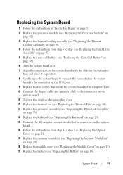
... on the system board. 11 Tighten the display cable grounding screw. 12 Replace the thermal fan (see "Replacing the Thermal Fan" on page 50). 13 Replace the palm-rest assembly (see "Replacing the Palm-Rest Assembly" on page 35). 14 Replace the keyboard (see "Replacing the Keyboard" on page 29). 15 Connect the AC-adapter connector cable to...
... on the system board. 11 Tighten the display cable grounding screw. 12 Replace the thermal fan (see "Replacing the Thermal Fan" on page 50). 13 Replace the palm-rest assembly (see "Replacing the Palm-Rest Assembly" on page 35). 14 Replace the keyboard (see "Replacing the Keyboard" on page 29). 15 Connect the AC-adapter connector cable to...

Service Manual
Page 4
Replacing the Optical Drive 21 6 Memory Module(s 23 Removing the Memory Module(s 23 Replacing the Memory Module(s 24 7 Keyboard 27 Removing the Keyboard 27 Replacing the Keyboard 29 8 Palm-Rest Assembly 31 Removing the Palm-Rest Assembly 31 Replacing the Palm-Rest Assembly 34 9 Hot-Key Board 37 Removing the Hot-Key Board 37 Replacing the Hot-Key Board 38 10 Power Button Board 41 Removing the Power Button Board 41 Replacing the Power Button Board 42 4 Contents
Replacing the Optical Drive 21 6 Memory Module(s 23 Removing the Memory Module(s 23 Replacing the Memory Module(s 24 7 Keyboard 27 Removing the Keyboard 27 Replacing the Keyboard 29 8 Palm-Rest Assembly 31 Removing the Palm-Rest Assembly 31 Replacing the Palm-Rest Assembly 34 9 Hot-Key Board 37 Removing the Hot-Key Board 37 Replacing the Hot-Key Board 38 10 Power Button Board 41 Removing the Power Button Board 41 Replacing the Power Button Board 42 4 Contents

Service Manual
Page 27
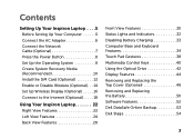
...keyboard are fragile, easily dislodged, and timeconsuming to disengage it may cause permanent damage to the keyboard tabs. 4 Slide a plastic scribe between the slots on the keyboard...dell.com/regulatory_compliance. Keyboard 27 CAUTION: To help prevent damage to servicing that shipped with your computer. Be careful when removing and handling the keyboard...not slide the plastic scribe under the keyboard tabs to remove the keyboard as possible. CAUTION: Only a ... 7 Keyboard WARNING: Before working inside your computer, read the safety information that is not authorized by Dell is ...
...keyboard are fragile, easily dislodged, and timeconsuming to disengage it may cause permanent damage to the keyboard tabs. 4 Slide a plastic scribe between the slots on the keyboard...dell.com/regulatory_compliance. Keyboard 27 CAUTION: To help prevent damage to servicing that shipped with your computer. Be careful when removing and handling the keyboard...not slide the plastic scribe under the keyboard tabs to remove the keyboard as possible. CAUTION: Only a ... 7 Keyboard WARNING: Before working inside your computer, read the safety information that is not authorized by Dell is ...

Service Manual
Page 29
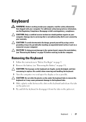
1 2 1 keyboard cable 2 keyboard-cable connector Replacing the Keyboard 1 Follow the instructions in "Before You Begin" on page 9. 2 Slide the keyboard cable into the slots on the palm-rest assembly. 4 Gently press around the edges of the keyboard and slide it upwards to secure the keyboard under the tabs on the system board. Press down on the connector latch to secure the keyboard cable to the connector on the system board. 3 Slide the tabs on the keyboard into the connector on the palm-rest assembly. 5 Close the display and turn the computer over. Keyboard 29
1 2 1 keyboard cable 2 keyboard-cable connector Replacing the Keyboard 1 Follow the instructions in "Before You Begin" on page 9. 2 Slide the keyboard cable into the slots on the palm-rest assembly. 4 Gently press around the edges of the keyboard and slide it upwards to secure the keyboard under the tabs on the system board. Press down on the connector latch to secure the keyboard cable to the connector on the system board. 3 Slide the tabs on the keyboard into the connector on the palm-rest assembly. 5 Close the display and turn the computer over. Keyboard 29

Service Manual
Page 30
6 Replace the battery (see "Replacing the Battery" on page 16). 30 Keyboard
6 Replace the battery (see "Replacing the Battery" on page 16). 30 Keyboard


