Service Manual
Page 1
...; Microsoft, Windows, and the Windows start button logo are not followed. Regulatory model: P09T series Regulatory type: P09T001 July 2010 Rev. Dell™ Inspiron™ 1018 Service Manual Before You Begin Battery Keyboard Hard Drive Palm Rest Assembly Power Button Board Memory Module Speaker Middle Cover Display Camera Module I/O Board Wireless Mini-Card Status Lights Board Support Brackets AC Adapter Connector System Board Coin-Cell Battery Flashing the BIOS Notes, Cautions, and Warnings NOTE: A NOTE indicates important information that helps you make better use of Microsoft...
...; Microsoft, Windows, and the Windows start button logo are not followed. Regulatory model: P09T series Regulatory type: P09T001 July 2010 Rev. Dell™ Inspiron™ 1018 Service Manual Before You Begin Battery Keyboard Hard Drive Palm Rest Assembly Power Button Board Memory Module Speaker Middle Cover Display Camera Module I/O Board Wireless Mini-Card Status Lights Board Support Brackets AC Adapter Connector System Board Coin-Cell Battery Flashing the BIOS Notes, Cautions, and Warnings NOTE: A NOTE indicates important information that helps you make better use of Microsoft...
Service Manual
Page 3
... cables have performed the steps in Turning Off Your Computer and Before Working Inside Your Computer. if you connect a cable, ensure that is not authorized by Dell™ is not covered by periodically touching an unpainted metal surface (such as a processor by its edges, not by performing the removal procedure in reverse order. Recommended Tools The procedures in this type of cable...
... cables have performed the steps in Turning Off Your Computer and Before Working Inside Your Computer. if you connect a cable, ensure that is not authorized by Dell™ is not covered by periodically touching an unpainted metal surface (such as a processor by its edges, not by performing the removal procedure in reverse order. Recommended Tools The procedures in this type of cable...
Service Manual
Page 6
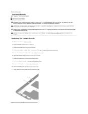
... technician should perform repairs on your computer. Removing the Camera Module 1. Remove the keyboard (see Removing the Middle Cover). 8. Remove the middle cover (see Removing the Keyboard). 4. Remove the battery (see Removing the Display Bezel). 10. Gently remove the camera module from step 4 to step 6 in Before You Begin. 2. Follow the instructions in Removing the Hard Drive). 5. Back to Contents Page Camera Module Dell™ Inspiron™ 1018 Service Manual Removing the Camera Module Replacing the Camera Module WARNING: Before working inside your computer...
... technician should perform repairs on your computer. Removing the Camera Module 1. Remove the keyboard (see Removing the Middle Cover). 8. Remove the middle cover (see Removing the Keyboard). 4. Remove the battery (see Removing the Display Bezel). 10. Gently remove the camera module from step 4 to step 6 in Before You Begin. 2. Follow the instructions in Removing the Hard Drive). 5. Back to Contents Page Camera Module Dell™ Inspiron™ 1018 Service Manual Removing the Camera Module Replacing the Camera Module WARNING: Before working inside your computer...
Service Manual
Page 9
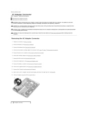
... adapter connector Remove the middle cover (see Removing the Keyboard). 4. Remove the keyboard (see Removing the Middle Cover). 9. Remove the hard-drive assembly (follow the instructions from the routing guide. 13. Back to Contents Page AC Adapter Connector Dell™ Inspiron™ 1018 Service Manual Removing the AC Adapter Connector Replacing the AC Adapter Connector WARNING: Before working inside your computer, read the safety information that is not authorized by Dell™ is not covered by periodically touching...
... adapter connector Remove the middle cover (see Removing the Keyboard). 4. Remove the keyboard (see Removing the Middle Cover). 9. Remove the hard-drive assembly (follow the instructions from the routing guide. 13. Back to Contents Page AC Adapter Connector Dell™ Inspiron™ 1018 Service Manual Removing the AC Adapter Connector Replacing the AC Adapter Connector WARNING: Before working inside your computer, read the safety information that is not authorized by Dell™ is not covered by periodically touching...
Service Manual
Page 11
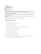
... Battery). 3. Damage due to the system board, remove the main battery (see Removing the Battery) before working inside the computer. Remove the keyboard (see Removing the Middle Cover). 8. Remove the middle cover (see Removing the Keyboard). 4. Remove the memory module (see the Regulatory Compliance Homepage at www.dell.com/regulatory_compliance. CAUTION: To avoid electrostatic discharge, ground yourself by using a wrist grounding strap or by your computer. Follow the instructions in Removing the Hard Drive...
... Battery). 3. Damage due to the system board, remove the main battery (see Removing the Battery) before working inside the computer. Remove the keyboard (see Removing the Middle Cover). 8. Remove the middle cover (see Removing the Keyboard). 4. Remove the memory module (see the Regulatory Compliance Homepage at www.dell.com/regulatory_compliance. CAUTION: To avoid electrostatic discharge, ground yourself by using a wrist grounding strap or by your computer. Follow the instructions in Removing the Hard Drive...
Service Manual
Page 18
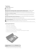
... four screws that secures the hard-drive assembly to the system board. 5. Remove the keyboard (see Removing the Battery). 3. Using the pull-tab, slide the hard-drive assembly to the side to disconnect it from the computer when the drive is On or in Before You Begin. 2. Back to Contents Page Hard Drive Dell™ Inspiron™ 1018 Service Manual Removing the Hard Drive Replacing the Hard Drive WARNING: Before working inside your computer, read...
... four screws that secures the hard-drive assembly to the system board. 5. Remove the keyboard (see Removing the Battery). 3. Using the pull-tab, slide the hard-drive assembly to the side to disconnect it from the computer when the drive is On or in Before You Begin. 2. Back to Contents Page Hard Drive Dell™ Inspiron™ 1018 Service Manual Removing the Hard Drive Replacing the Hard Drive WARNING: Before working inside your computer, read...
Service Manual
Page 19
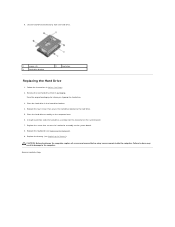
.... Follow the instructions in damage to the system board. 8. Replace the screw that no stray screws remain inside the computer. Back to the hard drive. 5. Replace the keyboard (see Replacing the Battery). Replace the four screws that secure the hard-drive bracket to Contents Page Lift the hard-drive bracket away from its packaging. Place the hard drive in the hard-drive bracket. 4. Replace the battery (see Replacing the Keyboard). 9. 8. Save the...
.... Follow the instructions in damage to the system board. 8. Replace the screw that no stray screws remain inside the computer. Back to the hard drive. 5. Replace the keyboard (see Replacing the Battery). Replace the four screws that secure the hard-drive bracket to Contents Page Lift the hard-drive bracket away from its packaging. Place the hard drive in the hard-drive bracket. 4. Replace the battery (see Replacing the Keyboard). 9. 8. Save the...
Service Manual
Page 22
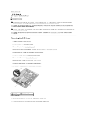
... the I/O board. 1 I/O board 2 grounding screw 3 I/O board cable 11. Follow the instructions in Removing the Hard Drive). 5. Remove the keyboard (see Removing the Memory Module). 7. Remove the display assembly (see the Regulatory Compliance Homepage at www.dell.com/regulatory_compliance. CAUTION: To avoid electrostatic discharge, ground yourself by using a wrist grounding strap or by your computer. Removing the I /O board cable from step 4 to the system board, remove the main battery (see Removing the Battery) before working inside the...
... the I/O board. 1 I/O board 2 grounding screw 3 I/O board cable 11. Follow the instructions in Removing the Hard Drive). 5. Remove the keyboard (see Removing the Memory Module). 7. Remove the display assembly (see the Regulatory Compliance Homepage at www.dell.com/regulatory_compliance. CAUTION: To avoid electrostatic discharge, ground yourself by using a wrist grounding strap or by your computer. Removing the I /O board cable from step 4 to the system board, remove the main battery (see Removing the Battery) before working inside the...
Service Manual
Page 27
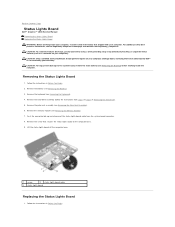
... computer. Back to Contents Page Status Lights Board Dell™ Inspiron™ 1018 Service Manual Removing the Status Lights Board Replacing the Status Lights Board WARNING: Before working inside your computer, read the safety information that secures the status lights board to the computer base. 9. Push the connector-tab up and disconnect the status lights board cable from step 4 to step 6 in Removing the Hard Drive). 5. Follow the instructions in Before You Begin.
... computer. Back to Contents Page Status Lights Board Dell™ Inspiron™ 1018 Service Manual Removing the Status Lights Board Replacing the Status Lights Board WARNING: Before working inside your computer, read the safety information that secures the status lights board to the computer base. 9. Push the connector-tab up and disconnect the status lights board cable from step 4 to step 6 in Removing the Hard Drive). 5. Follow the instructions in Before You Begin.
Service Manual
Page 29
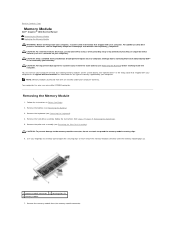
... the system board. Follow the instructions in Removing the Hard Drive). 5. Remove the keyboard (see Removing the Palm Rest Assembly). Use your fingertips to carefully spread apart the securing clips on your computer). You can increase your computer memory by your computer warranty. Remove the hard-drive assembly (follow the instructions from the memory-module connector. Back to Contents Page Memory Module Dell™ Inspiron™ 1018 Service Manual Removing the Memory Module Replacing the Memory Module WARNING: Before working inside...
... the system board. Follow the instructions in Removing the Hard Drive). 5. Remove the keyboard (see Removing the Palm Rest Assembly). Use your fingertips to carefully spread apart the securing clips on your computer). You can increase your computer memory by your computer warranty. Remove the hard-drive assembly (follow the instructions from the memory-module connector. Back to Contents Page Memory Module Dell™ Inspiron™ 1018 Service Manual Removing the Memory Module Replacing the Memory Module WARNING: Before working inside...
Service Manual
Page 30
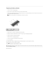
... computer. Align the notch in the memory module with the tab in Replacing the Hard Drive). 6. Replace the palm rest assembly (see Replacing the Battery). 8. module connector. 3. Slide the memory module firmly into the slot at a 45-degree angle, and press the memory module down until it detects the additional memory and automatically updates the system configuration information. As the computer boots, it clicks into place. Back to...
... computer. Align the notch in the memory module with the tab in Replacing the Hard Drive). 6. Replace the palm rest assembly (see Replacing the Battery). 8. module connector. 3. Slide the memory module firmly into the slot at a 45-degree angle, and press the memory module down until it detects the additional memory and automatically updates the system configuration information. As the computer boots, it clicks into place. Back to...
Service Manual
Page 32
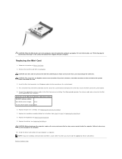
.... Replace the keyboard (see Replacing the Palm Rest Assembly). 7. Replace the battery (see "Protecting Against Electrostatic Discharge" in Replacing the Hard Drive). 8. Replacing the Mini-Card 1. CAUTION: Use firm and even pressure to step 7 in the safety information that no stray screws remain inside the computer. Replace the hard-drive assembly (follow the instructions from step 5 to slide the card into place. Install the drivers and utilities for the Mini- Remove the new Mini-Card...
.... Replace the keyboard (see Replacing the Palm Rest Assembly). 7. Replace the battery (see "Protecting Against Electrostatic Discharge" in Replacing the Hard Drive). 8. Replacing the Mini-Card 1. CAUTION: Use firm and even pressure to step 7 in the safety information that no stray screws remain inside the computer. Replace the hard-drive assembly (follow the instructions from step 5 to slide the card into place. Install the drivers and utilities for the Mini- Remove the new Mini-Card...
Service Manual
Page 39
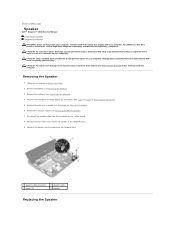
... working inside the computer. Follow the instructions in Removing the Hard Drive). 5. CAUTION: To avoid electrostatic discharge, ground yourself by using a wrist grounding strap or by your warranty. CAUTION: To help prevent damage to the system board, remove the main battery (see the Regulatory Compliance Homepage at www.dell.com/regulatory_compliance. Back to Contents Page Speaker Dell™ Inspiron™ 1018 Service Manual Removing the Speaker Replacing...
... working inside the computer. Follow the instructions in Removing the Hard Drive). 5. CAUTION: To avoid electrostatic discharge, ground yourself by using a wrist grounding strap or by your warranty. CAUTION: To help prevent damage to the system board, remove the main battery (see the Regulatory Compliance Homepage at www.dell.com/regulatory_compliance. Back to Contents Page Speaker Dell™ Inspiron™ 1018 Service Manual Removing the Speaker Replacing...
Service Manual
Page 41
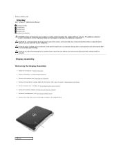
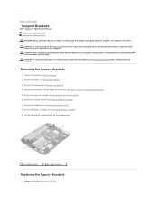
... battery (see Removing the Display Assembly). 9. Remove the keyboard (see Removing the Palm Rest Assembly). 6. Remove the palm rest assembly (see Removing the Keyboard). 4. Remove the middle cover (see the Regulatory Compliance Homepage at www.dell.com/regulatory_compliance. Lift the right and left support brackets off the computer base. 1 left support bracket 2 right support bracket Replacing the Support Brackets 1. Back to Contents Page Support Brackets Dell™ Inspiron™ 1018 Service Manual Removing the Support...
... battery (see Removing the Display Assembly). 9. Remove the keyboard (see Removing the Palm Rest Assembly). 6. Remove the palm rest assembly (see Removing the Keyboard). 4. Remove the middle cover (see the Regulatory Compliance Homepage at www.dell.com/regulatory_compliance. Lift the right and left support brackets off the computer base. 1 left support bracket 2 right support bracket Replacing the Support Brackets 1. Back to Contents Page Support Brackets Dell™ Inspiron™ 1018 Service Manual Removing the Support...
Service Manual
Page 43
... board. 13. Remove any installed card or blank from step 4 to step 6 in Removing the Hard Drive). 6. Remove the hard-drive assembly (follow the instructions from the Media Card reader slot. 3. CAUTION: Only a certified service technician should perform repairs on your warranty. Remove the memory module (see Removing the Support Brackets). 12. Remove the support brackets (see Removing the Memory Module). 8. Damage due to servicing that is not authorized by Dell™ is not covered by your computer. Follow the instructions...
... board. 13. Remove any installed card or blank from step 4 to step 6 in Removing the Hard Drive). 6. Remove the hard-drive assembly (follow the instructions from the Media Card reader slot. 3. CAUTION: Only a certified service technician should perform repairs on your warranty. Remove the memory module (see Removing the Support Brackets). 12. Remove the support brackets (see Removing the Memory Module). 8. Damage due to servicing that is not authorized by Dell™ is not covered by your computer. Follow the instructions...
Setup Guide
Page 5
... AC Adapter 6 Connect the Network Cable (Optional 7 Press the Power Button 8 Set Up the Operating System 9 Create System Recovery Media (Recommended 10 Enable or Disable Wireless (Optional 12 Connect to the Internet (Optional 14 Using Your Inspiron Laptop 16 Right View Features 16 Left View Features 17 Computer Base and Keyboard Features 18 Status Lights and Indicators 20 Back View Features 21 Touch Pad Gestures 22 Display Features 24 Removing and Replacing the Battery 26 Software Features 28 Dell Dock 29 Dell DataSafe Online Backup...
... AC Adapter 6 Connect the Network Cable (Optional 7 Press the Power Button 8 Set Up the Operating System 9 Create System Recovery Media (Recommended 10 Enable or Disable Wireless (Optional 12 Connect to the Internet (Optional 14 Using Your Inspiron Laptop 16 Right View Features 16 Left View Features 17 Computer Base and Keyboard Features 18 Status Lights and Indicators 20 Back View Features 21 Touch Pad Gestures 22 Display Features 24 Removing and Replacing the Battery 26 Software Features 28 Dell Dock 29 Dell DataSafe Online Backup...

Setup Guide
Page 33
... Clock failure Six Video card or chip failure Seven Processor failure Eight Display failure 31 BIOS ROM checksum failure Two No RAM detected NOTE: If you cannot solve your computer. If this occurs, write down the beep code and contact Dell (see the Service Manual at support.dell.com/manuals. INSPIRON Solving Problems This section provides troubleshooting information for your problem using the following guidelines, see "Using Support Tools" on...
... Clock failure Six Video card or chip failure Seven Processor failure Eight Display failure 31 BIOS ROM checksum failure Two No RAM detected NOTE: If you cannot solve your computer. If this occurs, write down the beep code and contact Dell (see the Service Manual at support.dell.com/manuals. INSPIRON Solving Problems This section provides troubleshooting information for your problem using the following guidelines, see "Using Support Tools" on...
Setup Guide
Page 41
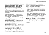
... consecutive times for the same error. CMOS checksum error - Replace the battery (see the Service Manual at support.dell.com/manuals). Possible hard-disk drive failure during HDD boot test. Contact Dell (see "Contacting Dell" on page 61). Possible harddisk drive failure during POST. Keyboard failure or loose cable. No bootable partition on hard drive, the hard drive cable is loose, or no bootable device exists. • If the hard drive is correct (see "Contacting Dell" on page 61). 39...
... consecutive times for the same error. CMOS checksum error - Replace the battery (see the Service Manual at support.dell.com/manuals). Possible hard-disk drive failure during HDD boot test. Contact Dell (see "Contacting Dell" on page 61). Possible harddisk drive failure during POST. Keyboard failure or loose cable. No bootable partition on hard drive, the hard drive cable is loose, or no bootable device exists. • If the hard drive is correct (see "Contacting Dell" on page 61). 39...
Setup Guide
Page 42
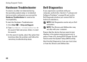
... assistance. Start the Dell Diagnostics from the Drivers and Utilities disc. 40 Using Support Tools Hardware Troubleshooter If a device is either not detected during POST (Power On Self Test) to start the Hardware Troubleshooter: 1. To start the search. 3. NOTE: The Drivers and Utilities disc may not ship with your hard drive or from your computer, perform the checks in the search field and press to enter the System Setup (BIOS) utility. NOTE: Dell Diagnostics works only...
... assistance. Start the Dell Diagnostics from the Drivers and Utilities disc. 40 Using Support Tools Hardware Troubleshooter If a device is either not detected during POST (Power On Self Test) to start the Hardware Troubleshooter: 1. To start the search. 3. NOTE: The Drivers and Utilities disc may not ship with your hard drive or from your computer, perform the checks in the search field and press to enter the System Setup (BIOS) utility. NOTE: Dell Diagnostics works only...
Setup Guide
Page 66
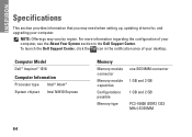
... Intel NM10 Express Memory Memory module connector Memory module capacities Configurations possible Memory type one SODIMM connector 1 GB and 2 GB 1 GB and 2 GB PC3-10600 (DDR3 1333 MHz) SODIMM 64 For more information regarding the configuration of your desktop. INSPIRON Specifications This section provides information that you may vary by region. NOTE: Offerings may need when setting up, updating drivers for, and upgrading your computer, see...
... Intel NM10 Express Memory Memory module connector Memory module capacities Configurations possible Memory type one SODIMM connector 1 GB and 2 GB 1 GB and 2 GB PC3-10600 (DDR3 1333 MHz) SODIMM 64 For more information regarding the configuration of your desktop. INSPIRON Specifications This section provides information that you may vary by region. NOTE: Offerings may need when setting up, updating drivers for, and upgrading your computer, see...


