
Service Manual
Page 5
... battery 48 Prerequisites...48 Procedure...48 28 Replacing the coin-cell battery 49 Procedure...49 Post-requisites...49 29 Removing the power-supply unit 50 Prerequisites...50 Procedure...50 30 Replacing the power-supply unit 52 Procedure...52 Post-requisites...53 31 Removing the top cover...54 Prerequisites...54 Procedure...54 32 Replacing the...
... battery 48 Prerequisites...48 Procedure...48 28 Replacing the coin-cell battery 49 Procedure...49 Post-requisites...49 29 Removing the power-supply unit 50 Prerequisites...50 Procedure...50 30 Replacing the power-supply unit 52 Procedure...52 Post-requisites...53 31 Removing the top cover...54 Prerequisites...54 Procedure...54 32 Replacing the...

Service Manual
Page 13
... 20. M.2 SATA connector 19. SATA3 connector 23. PCIe slot 4 28. SATA4 connector 21. processor-fan cable connector 6. power-button board cable connector 5. PCIe slot 3 27. processor-power cable connector 4. front chassis-fan connector 17. power-supply unit cable connector 12. jumper plug 22. front-audio connector System board components 13 5 System board components 1. light...
... 20. M.2 SATA connector 19. SATA3 connector 23. PCIe slot 4 28. SATA4 connector 21. processor-fan cable connector 6. power-button board cable connector 5. PCIe slot 3 27. processor-power cable connector 4. front chassis-fan connector 17. power-supply unit cable connector 12. jumper plug 22. front-audio connector System board components 13 5 System board components 1. light...

Service Manual
Page 14
... 3.5" hard drive Chassis Hard-drive bracket Hard drive 2.5" hard drive Chassis Hard-drive bracket Hard drive Graphics-card bracket Chassis Graphics card Chassis Fan Chassis Power-supply unit cover Chassis M2x3.5 6-32UNCx3.6 6-32UNCx3.6 6-32UNCx3.6 M3x3.5 6-32UNCx3.6 6-32UNCX3.6 6-32UNCx3.6 6-32UNCx6.3 1 2 4 1 4 2 1 2 (only with computers shipped with full-length graphics card) 1 2 14 Screw list...
... 3.5" hard drive Chassis Hard-drive bracket Hard drive 2.5" hard drive Chassis Hard-drive bracket Hard drive Graphics-card bracket Chassis Graphics card Chassis Fan Chassis Power-supply unit cover Chassis M2x3.5 6-32UNCx3.6 6-32UNCx3.6 6-32UNCx3.6 M3x3.5 6-32UNCx3.6 6-32UNCX3.6 6-32UNCx3.6 6-32UNCx6.3 1 2 4 1 4 2 1 2 (only with computers shipped with full-length graphics card) 1 2 14 Screw list...

Service Manual
Page 15
Screw list(continued) Component Secured to Power-supply unit Chassis Front cover Chassis Optical drive Chassis Front I/O panel Chassis Top cover Chassis Front bezel Chassis Antenna Chassis Left-side cover Chassis Bottom cover Chassis Top bracket Chassis System board Chassis Screw type 6-32UNCx6.3 6-32UNCX3.6 M3x5 M3x5 M3x5 M3x5 M3x5 M3x5 M3x5 M3x5 6-32UNCx6.3 Quantity 4 1 1 2 1 11 2 2 3 2 8 Screw image Screw list 15 Table 1.
Screw list(continued) Component Secured to Power-supply unit Chassis Front cover Chassis Optical drive Chassis Front I/O panel Chassis Top cover Chassis Front bezel Chassis Antenna Chassis Left-side cover Chassis Bottom cover Chassis Top bracket Chassis System board Chassis Screw type 6-32UNCx6.3 6-32UNCX3.6 M3x5 M3x5 M3x5 M3x5 M3x5 M3x5 M3x5 M3x5 6-32UNCx6.3 Quantity 4 1 1 2 1 11 2 2 3 2 8 Screw image Screw list 15 Table 1.

Service Manual
Page 50
... cover to the cables. NOTE: Remove the cables from the system board cable. 50 Removing the power-supply unit For more safety best practices, see the Regulatory Compliance home page at www.dell.com/regulatory_compliance. Lay the computer on the chassis to avoid potential damage to the chassis (Only for computers shipped with...
... cover to the cables. NOTE: Remove the cables from the system board cable. 50 Removing the power-supply unit For more safety best practices, see the Regulatory Compliance home page at www.dell.com/regulatory_compliance. Lay the computer on the chassis to avoid potential damage to the chassis (Only for computers shipped with...

Service Manual
Page 51
Remove the four screws (6-32UNCx6.3) that secure the power-supply unit to the chassis. 8. Removing the power-supply unit 51 Disconnect the power cable from the optical-drive cable. 7. Press the clamp and slide the power-supply unit towards the front of the chassis and lift the power-supply unit, along with the cables, off the chassis. 5. Disconnect the power cable from the hard-disk cable. 6.
Remove the four screws (6-32UNCx6.3) that secure the power-supply unit to the chassis. 8. Removing the power-supply unit 51 Disconnect the power cable from the optical-drive cable. 7. Press the clamp and slide the power-supply unit towards the front of the chassis and lift the power-supply unit, along with the cables, off the chassis. 5. Disconnect the power cable from the hard-disk cable. 6.

Service Manual
Page 52
... working inside your computer, read the safety information that secure the power-supply unit to the chassis. 4. For more safety best practices, see the Regulatory Compliance home page at www.dell.com/regulatory_compliance. Align the screw holes on the chassis. 3. Place the power supply on the chassis. 5. After working inside your computer, follow the steps...
... working inside your computer, read the safety information that secure the power-supply unit to the chassis. 4. For more safety best practices, see the Regulatory Compliance home page at www.dell.com/regulatory_compliance. Align the screw holes on the chassis. 3. Place the power supply on the chassis. 5. After working inside your computer, follow the steps...

Service Manual
Page 53
Post-requisites Replace the right-side cover. Place the computer in an upright position. Replace the two screws (6-32UNCx6.3) that secure the power-supply unit cover to the chassis. 10. Align the screw holes on the power-supply unit cover with the screw holes on the chassis. 9. 8. Replacing the power-supply unit 53
Post-requisites Replace the right-side cover. Place the computer in an upright position. Replace the two screws (6-32UNCx6.3) that secure the power-supply unit cover to the chassis. 10. Align the screw holes on the power-supply unit cover with the screw holes on the chassis. 9. 8. Replacing the power-supply unit 53

Service Manual
Page 98
Remove the power-supply unit. 3. Lift the top bracket off the chassis. 3. For more safety best practices, see the Regulatory Compliance home page at www.dell.com/regulatory_compliance. Remove the left side-chassis facing up and release the slots on the rear cover from the tabs on the chassis and remove ...
Remove the power-supply unit. 3. Lift the top bracket off the chassis. 3. For more safety best practices, see the Regulatory Compliance home page at www.dell.com/regulatory_compliance. Remove the left side-chassis facing up and release the slots on the rear cover from the tabs on the chassis and remove ...

Service Manual
Page 100
... After working inside your computer. Replace the top cover. 4. Replace the power-supply unit. 5. Replace the right-side cover. 100 Replacing the rear cover Replace the bottom cover. 2. For more safety best practices, see the Regulatory Compliance home page at www.dell.com/regulatory_compliance. Align the slots on the rear cover with the...
... After working inside your computer. Replace the top cover. 4. Replace the power-supply unit. 5. Replace the right-side cover. 100 Replacing the rear cover Replace the bottom cover. 2. For more safety best practices, see the Regulatory Compliance home page at www.dell.com/regulatory_compliance. Align the slots on the rear cover with the...

Service Manual
Page 101
...card. 6. Procedure NOTE: Note the routing of the connectors so that you replace the system board. Press the securing clip and disconnect the power-supply unit cable from the system board. Disconnect the USB 3.1 Type-C port cable from the system board. 8. NOTE: Replacing the system board ...the 2.5-inch hard-drive cable from the system board. 11. For more safety best practices, see the Regulatory Compliance home page at www.dell.com/regulatory_compliance. NOTE: Your computer's Service Tag is stored in Before working inside your computer, follow the steps in the system board....
...card. 6. Procedure NOTE: Note the routing of the connectors so that you replace the system board. Press the securing clip and disconnect the power-supply unit cable from the system board. Disconnect the USB 3.1 Type-C port cable from the system board. 8. NOTE: Replacing the system board ...the 2.5-inch hard-drive cable from the system board. 11. For more safety best practices, see the Regulatory Compliance home page at www.dell.com/regulatory_compliance. NOTE: Your computer's Service Tag is stored in Before working inside your computer, follow the steps in the system board....

Service Manual
Page 104
...system board. 8. Connect the light-bar cable to the system board. 11. Replace the processor. 2. Press the securing clip and disconnect the power-supply unit cable from the system board. 12. Connect the light-bar cable to the system board 14. Connect the front-audio cable to the ...cover. 104 Replacing the system board Connect the USB 2.0 cable to the system board. 16. Replace the wireless card. 5. Connect the optical-drive power cable to the system board. 15. Replace the solid-state drive. 6. Place the computer in an upright position. Connect the fan cable to the...
...system board. 8. Connect the light-bar cable to the system board. 11. Replace the processor. 2. Press the securing clip and disconnect the power-supply unit cable from the system board. 12. Connect the light-bar cable to the system board 14. Connect the front-audio cable to the ...cover. 104 Replacing the system board Connect the USB 2.0 cable to the system board. 16. Replace the wireless card. 5. Connect the optical-drive power cable to the system board. 15. Replace the solid-state drive. 6. Place the computer in an upright position. Connect the fan cable to the...
Service Manual
Page 112
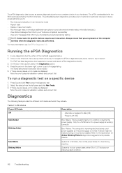
... LED states and what they indicate. This does not indicate a fault condition. 112 Troubleshooting For more information, see Dell EPSA Diagnostic 3.0. Once on the power supply is launched by the BIOS internally. Press Esc and click Yes to the page listing. Table 7. Boot Failure: ...devices require user interaction. Solid White Blinking White System is a system fault error condition, including the power supply. Note the error code and validation number and contact Dell. The ePSA is embedded with the BIOS and is working correctly. Note the error code and validation...
... LED states and what they indicate. This does not indicate a fault condition. 112 Troubleshooting For more information, see Dell EPSA Diagnostic 3.0. Once on the power supply is launched by the BIOS internally. Press Esc and click Yes to the page listing. Table 7. Boot Failure: ...devices require user interaction. Solid White Blinking White System is a system fault error condition, including the power supply. Note the error code and validation number and contact Dell. The ePSA is embedded with the BIOS and is working correctly. Note the error code and validation...

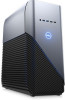
Inspiron Gaming Desktop Setup and Specifications
Page 11
.... 4 Service Tag label The Service Tag is a unique alphanumeric identifier that enables Dell service technicians to identify the hardware components in your computer and access warranty information. 5 Power-supply diagnostics light Indicates the power-supply state. 6 Power-supply diagnostics button Press to check the power‑supply state. 7 Expansion-card slots (5) Connect a PCI/PCI-Express card such as graphics...
.... 4 Service Tag label The Service Tag is a unique alphanumeric identifier that enables Dell service technicians to identify the hardware components in your computer and access warranty information. 5 Power-supply diagnostics light Indicates the power-supply state. 6 Power-supply diagnostics button Press to check the power‑supply state. 7 Expansion-card slots (5) Connect a PCI/PCI-Express card such as graphics...


