Service Manual
Page 3
... protection...7 ESD field service kit ...7 Transporting sensitive components...8 After working inside your computer...8 2 Removing and installing components 9 Recommended tools...9 Screw list...9 Base cover...10 Removing the base cover...10 Replacing the base cover...13 Battery...16 Removing the battery...16 Replacing the battery...17 Memory modules...19 Removing the memory modules...19 Replacing the memory modules...20 Wireless card...20 Removing the wireless card...20 Replacing the wireless card...21 Fan...22 Removing the fan...22 Replacing the fan...23 Solid-state drive/Intel Optane...24...
... protection...7 ESD field service kit ...7 Transporting sensitive components...8 After working inside your computer...8 2 Removing and installing components 9 Recommended tools...9 Screw list...9 Base cover...10 Removing the base cover...10 Replacing the base cover...13 Battery...16 Removing the battery...16 Replacing the battery...17 Memory modules...19 Removing the memory modules...19 Replacing the memory modules...20 Wireless card...20 Removing the wireless card...20 Replacing the wireless card...21 Fan...22 Removing the fan...22 Replacing the fan...23 Solid-state drive/Intel Optane...24...
Service Manual
Page 4
... camera...62 Replacing the camera...63 Display panel...64 Removing the display panel...64 Replacing the display panel...66 Display cable...68 Removing the display cable...68 Replacing the display cable...69 Display back-cover and antenna assembly...70 Removing the display back-cover and antenna assembly 70 Replacing the display back-cover and antenna assembly 71 3 Device drivers...73 Downloading the audio driver...73 Downloading the network driver...73 Downloading the chipset driver...74 Downloading the media-card reader driver...74 Downloading the WiFi driver...75 Downloading the USB driver...
... camera...62 Replacing the camera...63 Display panel...64 Removing the display panel...64 Replacing the display panel...66 Display cable...68 Removing the display cable...68 Replacing the display cable...69 Display back-cover and antenna assembly...70 Removing the display back-cover and antenna assembly 70 Replacing the display back-cover and antenna assembly 71 3 Device drivers...73 Downloading the audio driver...73 Downloading the network driver...73 Downloading the chipset driver...74 Downloading the media-card reader driver...74 Downloading the WiFi driver...75 Downloading the USB driver...

Service Manual
Page 6
... by periodically touching an unpainted metal surface, such as keyboard, mouse, and monitor from their electrical outlets. 4. When disconnecting cables, keep them evenly aligned to avoid bending any installed card from your computer. Save and close all open applications. 2. Some cables have read the safety information that shipped with your computer. Click Start > Power > Shut down instructions. 3. Disconnect all attached network devices and peripherals...
... by periodically touching an unpainted metal surface, such as keyboard, mouse, and monitor from their electrical outlets. 4. When disconnecting cables, keep them evenly aligned to avoid bending any installed card from your computer. Save and close all open applications. 2. Some cables have read the safety information that shipped with your computer. Click Start > Power > Shut down instructions. 3. Disconnect all attached network devices and peripherals...
Service Manual
Page 7
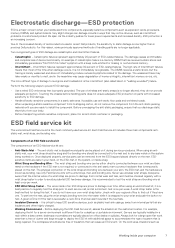
... skin, the ESD mat, and the hardware is properly grounded. desktops or portables are insulators and often highly charged. • Working Environment - The DIMM receives a static shock, but the tracing is successful; It is free of an ESD strap are typically installed in previous Dell products. Touching the chassis before handling parts does not ensure adequate ESD protection...
... skin, the ESD mat, and the hardware is properly grounded. desktops or portables are insulators and often highly charged. • Working Environment - The DIMM receives a static shock, but the tracing is successful; It is free of an ESD strap are typically installed in previous Dell products. Touching the chassis before handling parts does not ensure adequate ESD protection...
Service Manual
Page 8
... place these parts in anti-static bags for safe transport. Connect any external devices, peripherals, or cables you removed before working inside your computer CAUTION: Leaving stray or loose screws inside an anti-static bag. • Transporting Sensitive Components - In addition, it is recommended that they use a mechanical lifting device. 1. Replace all screws and ensure that the new part arrived in. Connect your computer...
... place these parts in anti-static bags for safe transport. Connect any external devices, peripherals, or cables you removed before working inside your computer CAUTION: Leaving stray or loose screws inside an anti-static bag. • Transporting Sensitive Components - In addition, it is recommended that they use a mechanical lifting device. 1. Replace all screws and ensure that the new part arrived in. Connect your computer...
Service Manual
Page 19
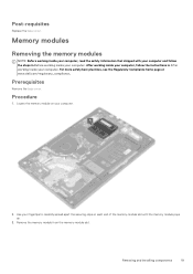
... Remove the base cover. Locate the memory module on your fingertips to carefully spread apart the securing-clips on each end of the memory-module slot until the memory module pops up. 3. Post-requisites Replace the base cover. For more safety best practices, see the Regulatory Compliance home page at www.dell.com/regulatory_compliance. Procedure 1. Use your computer. 2. Removing and installing components 19 Remove the memory module from the memory-module slot. After working...
... Remove the base cover. Locate the memory module on your fingertips to carefully spread apart the securing-clips on each end of the memory-module slot until the memory module pops up. 3. Post-requisites Replace the base cover. For more safety best practices, see the Regulatory Compliance home page at www.dell.com/regulatory_compliance. Procedure 1. Use your computer. 2. Removing and installing components 19 Remove the memory module from the memory-module slot. After working...
Service Manual
Page 20
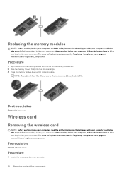
... Removing and installing components For more safety best practices, see the Regulatory Compliance home page at an angle. 3. Wireless card Removing the wireless card NOTE: Before working inside your computer, read the safety information that shipped with your computer and follow the steps in Before working inside your computer. Procedure 1. Press the memory module down until it . Locate the wireless card on the memory-module slot. 2. Replacing the memory modules...
... Removing and installing components For more safety best practices, see the Regulatory Compliance home page at an angle. 3. Wireless card Removing the wireless card NOTE: Before working inside your computer, read the safety information that shipped with your computer and follow the steps in Before working inside your computer. Procedure 1. Press the memory module down until it . Locate the wireless card on the memory-module slot. 2. Replacing the memory modules...
Service Manual
Page 28
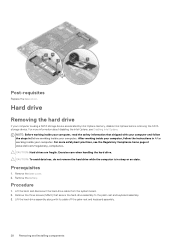
... www.dell.com/regulatory_compliance. Lift the latch and disconnect the hard-drive cable from the system board. 2. Prerequisites 1. Remove the base cover. 2. NOTE: Before working inside your computer. CAUTION: Hard drives are fragile. CAUTION: To avoid data loss, do not remove the hard drive while the computer is using a SATA storage device accelerated by Intel Optane memory, disable Intel Optane before removing the SATA storage device. Remove the battery. Procedure 1. Remove the...
... www.dell.com/regulatory_compliance. Lift the latch and disconnect the hard-drive cable from the system board. 2. Prerequisites 1. Remove the base cover. 2. NOTE: Before working inside your computer. CAUTION: Hard drives are fragile. CAUTION: To avoid data loss, do not remove the hard drive while the computer is using a SATA storage device accelerated by Intel Optane memory, disable Intel Optane before removing the SATA storage device. Remove the battery. Procedure 1. Remove the...
Service Manual
Page 45
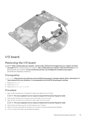
... computers shipped with Intel optane. Remove the battery. 3. Remove the hard drive with the optional fingerprint reader. 2. Open the latch and disconnect the power-button board cable from the I /O board. 3. NOTE: This step is recommended to default. Prerequisites CAUTION: Removing the coin-cell battery resets the BIOS setup program's settings to note the BIOS setup program's settings. 1. Open the latch and disconnect the I/O-board cable from the I /O board. 5. Remove the base cover. 2. I/O board Removing the I/O board NOTE: Before working inside your computer, read...
... computers shipped with Intel optane. Remove the battery. 3. Remove the hard drive with the optional fingerprint reader. 2. Open the latch and disconnect the power-button board cable from the I /O board. 3. NOTE: This step is recommended to default. Prerequisites CAUTION: Removing the coin-cell battery resets the BIOS setup program's settings to note the BIOS setup program's settings. 1. Open the latch and disconnect the I/O-board cable from the I /O board. 5. Remove the base cover. 2. I/O board Removing the I/O board NOTE: Before working inside your computer, read...
Service Manual
Page 48
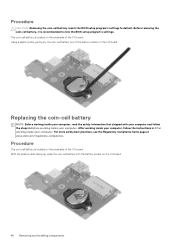
... I /O board. 48 Removing and installing components Procedure The coin-cell battery is recommended to default. Before removing the coin-cell battery, it is located on the I /O board. Replacing the coin-cell battery NOTE: Before working inside your computer, read the safety information that shipped with your computer and follow the instructions in Before working inside your computer. Procedure CAUTION: Removing the coin-cell battery resets the BIOS setup program's settings...
... I /O board. 48 Removing and installing components Procedure The coin-cell battery is recommended to default. Before removing the coin-cell battery, it is located on the I /O board. Replacing the coin-cell battery NOTE: Before working inside your computer, read the safety information that shipped with your computer and follow the instructions in Before working inside your computer. Procedure CAUTION: Removing the coin-cell battery resets the BIOS setup program's settings...
Service Manual
Page 51
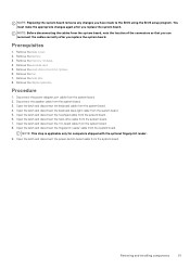
... the optional fingerprint reader. 9. Prerequisites 1. Open the latch and disconnect the keyboard back-light cable from the system board. 3. Open the latch and disconnect the fingerprint-reader cable from the system board. NOTE: Replacing the system board removes any changes you have made to the BIOS using the BIOS setup program. Open the latch and disconnect the power-button board cable from the system board. Remove the wireless card. 5. Remove the display assembly. Procedure 1. Open the latch and disconnect the hard-drive cable from...
... the optional fingerprint reader. 9. Prerequisites 1. Open the latch and disconnect the keyboard back-light cable from the system board. 3. Open the latch and disconnect the fingerprint-reader cable from the system board. NOTE: Replacing the system board removes any changes you have made to the BIOS using the BIOS setup program. Open the latch and disconnect the power-button board cable from the system board. Remove the wireless card. 5. Remove the display assembly. Procedure 1. Open the latch and disconnect the hard-drive cable from...
Service Manual
Page 73
... identify if manual installation is necessary. 13. Enter the Service Tag of your computer starts to download and install SupportAssist. Click Drivers & downloads. 5. Review the installation summary to identify if manual installation is complete, navigate to make changes on the screen to download and install all driver updates detected for your computer. 2. Click the Detect Drivers button. 6. If necessary, your computer, and then click Submit. If prompted, approve requests from User Account Control to...
... identify if manual installation is necessary. 13. Enter the Service Tag of your computer starts to download and install SupportAssist. Click Drivers & downloads. 5. Review the installation summary to identify if manual installation is complete, navigate to make changes on the screen to download and install all driver updates detected for your computer. 2. Click the Detect Drivers button. 6. If necessary, your computer, and then click Submit. If prompted, approve requests from User Account Control to...
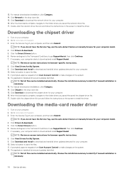
Service Manual
Page 74
... User Account Control to identify if manual installation is complete, navigate to download and install SupportAssist. The application installs all driver updates detected for your computer. 10. Turn on your computer starts to download and install all drivers and updates identified. Click the Detect Drivers button. 6. Click Download and Install to install the driver. Double-click the network driver file icon and follow the instructions on the system. 12. Review the installation summary to make changes on the screen...
... User Account Control to identify if manual installation is complete, navigate to download and install SupportAssist. The application installs all driver updates detected for your computer. 10. Turn on your computer starts to download and install all drivers and updates identified. Click the Detect Drivers button. 6. Click Download and Install to install the driver. Double-click the network driver file icon and follow the instructions on the system. 12. Review the installation summary to make changes on the screen...
Service Manual
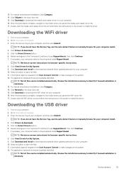
Page 75
... browser-specific instructions. 8. Click the Detect Drivers button. 6. Click Download and Install to the folder where you saved the media-card reader driver file. 17. Click Network in the drop-down list. 15. After the download is necessary. Downloading the USB driver 1. If prompted, approve requests from User Account Control to the folder where you saved the WiFi driver file. 17. Turn on -screen instructions for your computer model. 4. Review the installation summary to www.dell.com/support...
... browser-specific instructions. 8. Click the Detect Drivers button. 6. Click Download and Install to the folder where you saved the media-card reader driver file. 17. Click Network in the drop-down list. 15. After the download is necessary. Downloading the USB driver 1. If prompted, approve requests from User Account Control to the folder where you saved the WiFi driver file. 17. Turn on -screen instructions for your computer model. 4. Review the installation summary to www.dell.com/support...
Service Manual
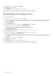
Page 76
... requests from User Account Control to install the driver. 76 Device drivers Double-click the graphics driver file icon and follow the instructions on -screen instructions for My System. 9. NOTE: If you saved the USB driver file. 17. Review the installation summary to identify if manual installation is complete, navigate to download and install SupportAssist. 13. Enter the Service Tag of your computer. 2. Click Chipset in the drop-down list. 15.
... requests from User Account Control to install the driver. 76 Device drivers Double-click the graphics driver file icon and follow the instructions on -screen instructions for My System. 9. NOTE: If you saved the USB driver file. 17. Review the installation summary to identify if manual installation is complete, navigate to download and install SupportAssist. 13. Enter the Service Tag of your computer. 2. Click Chipset in the drop-down list. 15.
Service Manual
Page 77
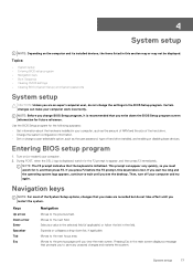
...; System setup • Entering BIOS setup program • Navigation keys • Boot Sequence • Clearing CMOS settings • Clearing BIOS (System Setup) and System passwords System setup CAUTION: Unless you press F2 before the F2 prompt, this section may or may not be displayed. If you are recorded but do not change the settings in the field. Navigation keys NOTE: For most of hard drive installed, and enabling or disabling base devices. Moves to...
...; System setup • Entering BIOS setup program • Navigation keys • Boot Sequence • Clearing CMOS settings • Clearing BIOS (System Setup) and System passwords System setup CAUTION: Unless you press F2 before the F2 prompt, this section may or may not be displayed. If you are recorded but do not change the settings in the field. Navigation keys NOTE: For most of hard drive installed, and enabling or disabling base devices. Moves to...

Service Manual
Page 78
... drive or hard drive). Clearing BIOS (System Setup) and System passwords To clear the system or BIOS passwords, contact Dell technical support as described at www.dell.com/contactdell. NOTE: For information on how to reset Windows or application passwords, refer to the documentation accompanying Windows or your computer. 1. During the Power-on your application. 78 System setup Replace the coin-cell battery. 6. Connect the battery cable to access the System Setup screen. Replace the base cover. Clearing CMOS settings CAUTION: Clearing CMOS settings will display...
... drive or hard drive). Clearing BIOS (System Setup) and System passwords To clear the system or BIOS passwords, contact Dell technical support as described at www.dell.com/contactdell. NOTE: For information on how to reset Windows or application passwords, refer to the documentation accompanying Windows or your computer. 1. During the Power-on your application. 78 System setup Replace the coin-cell battery. 6. Connect the battery cable to access the System Setup screen. Replace the base cover. Clearing CMOS settings CAUTION: Clearing CMOS settings will display...
Service Manual
Page 79
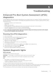
..., or turned off indicating no memory or RAM is launched by a pause. Note the error code and validation number and contact Dell. Off • Power adapter is connected and the battery is fully charged. • Computer is running on battery and the battery has more than 5 percent charge. The following table shows different power and battery-status light patterns and associated problems. Troubleshooting 79 Running the ePSA diagnostics 1. Select the device from...
..., or turned off indicating no memory or RAM is launched by a pause. Note the error code and validation number and contact Dell. Off • Power adapter is connected and the battery is fully charged. • Computer is running on battery and the battery has more than 5 percent charge. The following table shows different power and battery-status light patterns and associated problems. Troubleshooting 79 Running the ePSA diagnostics 1. Select the device from...
Service Manual
Page 80
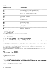
...-Access Memory) failure Invalid memory installed System-board or chipset error Display failure Coin-cell battery failure PCI, video card/chip failure Recovery image not found Recovery image found but invalid Power-rail failure System BIOS Flash incomplete Management Engine (ME) error Camera status light: Indicates whether the camera is in all Dell computers installed with Windows 10 operating system. Camera is in use . • Solid white - Dell SupportAssist OS Recovery is enabled or disabled. • Solid white - NOTE: If you replace...
...-Access Memory) failure Invalid memory installed System-board or chipset error Display failure Coin-cell battery failure PCI, video card/chip failure Recovery image not found Recovery image found but invalid Power-rail failure System BIOS Flash incomplete Management Engine (ME) error Camera status light: Indicates whether the camera is in all Dell computers installed with Windows 10 operating system. Camera is in use . • Solid white - Dell SupportAssist OS Recovery is enabled or disabled. • Solid white - NOTE: If you replace...
Service Manual
Page 81
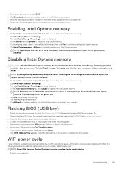
... "Flashing the BIOS" to download the latest BIOS setup program file. 2. Follow the procedure from the computer. 1. Connect the bootable USB drive to continue enabling Intel Optane memory. 5. Follow the instructions on how to see the knowledge base article SLN143196 at www.dell.com/support. 3. Troubleshooting 81 On the taskbar, click the search box, and then type Intel Rapid Storage Technology. 2. Boot to enable the Intel Optane memory. 4. WiFi power...
... "Flashing the BIOS" to download the latest BIOS setup program file. 2. Follow the procedure from the computer. 1. Connect the bootable USB drive to continue enabling Intel Optane memory. 5. Follow the instructions on how to see the knowledge base article SLN143196 at www.dell.com/support. 3. Troubleshooting 81 On the taskbar, click the search box, and then type Intel Rapid Storage Technology. 2. Boot to enable the Intel Optane memory. 4. WiFi power...


