Service Manual
Page 1
... these materials in any proprietary interest in this text: Dell, the DELL logo, and Inspiron are either the entities claiming the marks and names or their products. Dell Inc. disclaims any manner whatsoever without notice. © 2009 Dell Inc. Other trademarks and trade names may be used...and/or other than its own. February 2009 Rev. Microsoft and Windows are trademarks of Dell Inc. Information in trademarks and trade names other countries. Dell™ Inspiron™ 535/537/545/546 Service Manual Technical Overview Before You Begin Computer Cover Front Bezel Memory PCI and...
... these materials in any proprietary interest in this text: Dell, the DELL logo, and Inspiron are either the entities claiming the marks and names or their products. Dell Inc. disclaims any manner whatsoever without notice. © 2009 Dell Inc. Other trademarks and trade names may be used...and/or other than its own. February 2009 Rev. Microsoft and Windows are trademarks of Dell Inc. Information in trademarks and trade names other countries. Dell™ Inspiron™ 535/537/545/546 Service Manual Technical Overview Before You Begin Computer Cover Front Bezel Memory PCI and...
Service Manual
Page 2
... own personal safety. Also, before you pull connectors apart, keep them off your computer, see the Regulatory Compliance Homepage at support.dell.com. Turn off . Recommended Tools The procedures in this type of your computer. 1. CAUTION: To avoid damaging the computer, ... cable, ensure that ships with your computer (see the Dell Support website at www.dell.com/regulatory_compliance. As you disconnect the cable. Back to Contents Page Before You Begin Dell™ Inspiron™ 535/537/545/546 Service Manual Technical Specifications Recommended Tools Turning Off Your...
... own personal safety. Also, before you pull connectors apart, keep them off your computer, see the Regulatory Compliance Homepage at support.dell.com. Turn off . Recommended Tools The procedures in this type of your computer. 1. CAUTION: To avoid damaging the computer, ... cable, ensure that ships with your computer (see the Dell Support website at www.dell.com/regulatory_compliance. As you disconnect the cable. Back to Contents Page Before You Begin Dell™ Inspiron™ 535/537/545/546 Service Manual Technical Specifications Recommended Tools Turning Off Your...
Service Manual
Page 4
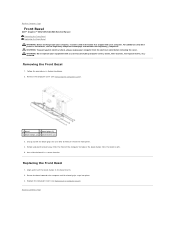
Grasp and lift the bezel grips one at www.dell.com/regulatory_compliance. Back to release it from the front panel. 4. WARNING: To guard against electrical shock, always unplug your equipment with your computer. Removing the ... aside the bezel in a secure location. Rotate and pull the bezel away from the front of the computer to Contents Page Front Bezel Dell™ Inspiron™ 535/537/545/546 Service Manual Removing the Front Bezel Replacing the Front Bezel WARNING: Before working inside your computer, read the safety information that shipped...
Grasp and lift the bezel grips one at www.dell.com/regulatory_compliance. Back to release it from the front panel. 4. WARNING: To guard against electrical shock, always unplug your equipment with your computer. Removing the ... aside the bezel in a secure location. Rotate and pull the bezel away from the front of the computer to Contents Page Front Bezel Dell™ Inspiron™ 535/537/545/546 Service Manual Removing the Front Bezel Replacing the Front Bezel WARNING: Before working inside your computer, read the safety information that shipped...
Service Manual
Page 5
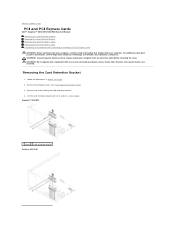
...always unplug your computer. Removing the Card Retention Bracket 1. Back to Contents Page PCI and PCI Express Cards Dell™ Inspiron™ 535/537/545/546 Service Manual Removing the Card Retention Bracket Replacing the Card Retention Bracket Removing PCI and PCI Express ...Removing the Computer Cover). 3. Remove the computer cover (see the Regulatory Compliance Homepage at www.dell.com/regulatory_compliance. Inspiron™ 535/537 1 screw 2 card retention bracket Inspiron 545/546 WARNING: Do not operate your equipment with your computer from the electrical outlet before ...
...always unplug your computer. Removing the Card Retention Bracket 1. Back to Contents Page PCI and PCI Express Cards Dell™ Inspiron™ 535/537/545/546 Service Manual Removing the Card Retention Bracket Replacing the Card Retention Bracket Removing PCI and PCI Express ...Removing the Computer Cover). 3. Remove the computer cover (see the Regulatory Compliance Homepage at www.dell.com/regulatory_compliance. Inspiron™ 535/537 1 screw 2 card retention bracket Inspiron 545/546 WARNING: Do not operate your equipment with your computer from the electrical outlet before ...
Service Manual
Page 9
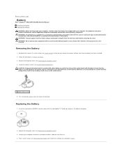
... computer. Remove the computer cover (see System Board Components). Press the battery release lever to Contents Page Battery Dell™ Inspiron™ 535/537/545/546 Service Manual Removing the Battery Replacing the Battery WARNING: Before working inside your computer from the electrical ... You Begin. 3. Replacing the Battery 1. Removing the Battery 1. Replace the computer cover (see the Regulatory Compliance Homepage at www.dell.com/regulatory_compliance. Enter system setup (see System Setup) so that you attempt to touch the system board with any cover(s) (including...
... computer. Remove the computer cover (see System Board Components). Press the battery release lever to Contents Page Battery Dell™ Inspiron™ 535/537/545/546 Service Manual Removing the Battery Replacing the Battery WARNING: Before working inside your computer from the electrical ... You Begin. 3. Replacing the Battery 1. Removing the Battery 1. Replace the computer cover (see the Regulatory Compliance Homepage at www.dell.com/regulatory_compliance. Enter system setup (see System Setup) so that you attempt to touch the system board with any cover(s) (including...
Service Manual
Page 11
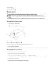
... unplug your equipment with the slots located along the edge of the computer. 4. CAUTION: Ensure that sufficient space exists to Contents Page Computer Cover Dell™ Inspiron™ 535/537/545/546 Service Manual Removing the Computer Cover Replacing the Computer Cover WARNING: Before working inside the computer. 3. Lay your computer on its...
... unplug your equipment with the slots located along the edge of the computer. 4. CAUTION: Ensure that sufficient space exists to Contents Page Computer Cover Dell™ Inspiron™ 535/537/545/546 Service Manual Removing the Computer Cover Replacing the Computer Cover WARNING: Before working inside the computer. 3. Lay your computer on its...
Service Manual
Page 13
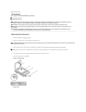
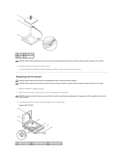
.... 2. CAUTION: Despite having a plastic shield, the heat sink assembly may be very hot during normal operation. Back to Contents Page Processor Dell™ Inspiron™ 535/537/545/546 Service Manual Removing the Processor Replacing the Processor WARNING: Before working inside your computer, read the safety information that secures it. 5.... removed. WARNING: To guard against electrical shock, always unplug your computer. For technical service, see Removing the Processor Fan and Heat Sink Assembly). Inspiron™ 535/537/545 1 processor cover 2 processor 3 socket 4 release lever...
.... 2. CAUTION: Despite having a plastic shield, the heat sink assembly may be very hot during normal operation. Back to Contents Page Processor Dell™ Inspiron™ 535/537/545/546 Service Manual Removing the Processor Replacing the Processor WARNING: Before working inside your computer, read the safety information that secures it. 5.... removed. WARNING: To guard against electrical shock, always unplug your computer. For technical service, see Removing the Processor Fan and Heat Sink Assembly). Inspiron™ 535/537/545 1 processor cover 2 processor 3 socket 4 release lever...
Service Manual
Page 14
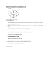
... in the release position so that position. CAUTION: When replacing the processor, do not touch any objects to fall on the pins in the socket. 6. Inspiron 535/537/545 1 front alignment notch 2 processor pin-1 indicator 3 rear alignment notch Unpack the new processor, being careful not to touch the underside of the pins...
... in the release position so that position. CAUTION: When replacing the processor, do not touch any objects to fall on the pins in the socket. 6. Inspiron 535/537/545 1 front alignment notch 2 processor pin-1 indicator 3 rear alignment notch Unpack the new processor, being careful not to touch the underside of the pins...
Service Manual
Page 15
...thermal grease from the bottom of the processor and socket. Replace the processor fan/heat sink assembly (see Replacing the Computer Cover). For Inspiron 535/537/545, orient the front and rear alignment-notches on the processor with the socket, and do not use excessive force when you apply... processor. 6. CAUTION: Ensure that the processor aligns properly with the front and rear alignment-notches on the socket. 8. 4 processor cover 7 socket Inspiron 546 5 center cover latch 8 tab 6 processor 9 release lever 1 socket 2 processor pin-1 indicator 3 processor 4 release lever 4.
...thermal grease from the bottom of the processor and socket. Replace the processor fan/heat sink assembly (see Replacing the Computer Cover). For Inspiron 535/537/545, orient the front and rear alignment-notches on the processor with the socket, and do not use excessive force when you apply... processor. 6. CAUTION: Ensure that the processor aligns properly with the front and rear alignment-notches on the socket. 8. 4 processor cover 7 socket Inspiron 546 5 center cover latch 8 tab 6 processor 9 release lever 1 socket 2 processor pin-1 indicator 3 processor 4 release lever 4.
Service Manual
Page 16
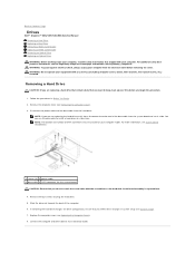
...unplug your computer from the system board and set it aside. You can use the data cable to install a hard drive at www.dell.com/regulatory_compliance. Remove the computer cover (see Replacing the Computer Cover). 8. For additional safety best practices information, see System Board Components. ...model. Removing a Hard Drive CAUTION: If you reflect these changes in Before You Begin. 2. Back to Contents Page Drives Dell™ Inspiron™ 535/537/545/546 Service Manual Removing a Hard Drive Replacing a Hard Drive Removing a Media Card Reader Replacing a Media Card Reader ...
...unplug your computer from the system board and set it aside. You can use the data cable to install a hard drive at www.dell.com/regulatory_compliance. Remove the computer cover (see Replacing the Computer Cover). 8. For additional safety best practices information, see System Board Components. ...model. Removing a Hard Drive CAUTION: If you reflect these changes in Before You Begin. 2. Back to Contents Page Drives Dell™ Inspiron™ 535/537/545/546 Service Manual Removing a Hard Drive Replacing a Hard Drive Removing a Media Card Reader Replacing a Media Card Reader ...
Service Manual
Page 20
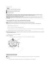
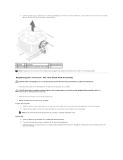
...like the one single unit. Remove the computer cover (see the Regulatory Compliance Homepage at www.dell.com/regulatory_compliance. Back to Contents Page Fans Dell™ Inspiron™ 535/537/545/546 Service Manual Removing the Processor Fan and Heat Sink Assembly Replacing the Processor Fan ...computer. Follow the procedures in the illustration above. Rotate the clamp lever 180 degrees counter-clockwise to remove the fan separately. Inspiron™ 535/537/545 a. Disconnect the processor fan and heat sink assembly cable from the processor fan connector on the system board (see System...
...like the one single unit. Remove the computer cover (see the Regulatory Compliance Homepage at www.dell.com/regulatory_compliance. Back to Contents Page Fans Dell™ Inspiron™ 535/537/545/546 Service Manual Removing the Processor Fan and Heat Sink Assembly Replacing the Processor Fan ...computer. Follow the procedures in the illustration above. Rotate the clamp lever 180 degrees counter-clockwise to remove the fan separately. Inspiron™ 535/537/545 a. Disconnect the processor fan and heat sink assembly cable from the processor fan connector on the system board (see System...
Service Manual
Page 21
.... 1. c. b. Replacing the Processor Fan and Heat Sink Assembly CAUTION: When reinstalling the fan, ensure that you apply new thermal grease. Inspiron 546 a. Clean the thermal grease from the computer. Replace the processor fan and heat sink assembly. Ensure that you do not pinch the... fan and heat sink assembly to the four metal screw hole projections on the processor fan and heat sink assembly to the system board. Inspiron 535/537/545 a. CAUTION: Ensure that the two clamp grips are aligned with the thermal grease facing upward. 1 bracket 2 clamp grip 3 bracket...
.... 1. c. b. Replacing the Processor Fan and Heat Sink Assembly CAUTION: When reinstalling the fan, ensure that you apply new thermal grease. Inspiron 546 a. Clean the thermal grease from the computer. Replace the processor fan and heat sink assembly. Ensure that you do not pinch the... fan and heat sink assembly to the four metal screw hole projections on the processor fan and heat sink assembly to the system board. Inspiron 535/537/545 a. CAUTION: Ensure that the two clamp grips are aligned with the thermal grease facing upward. 1 bracket 2 clamp grip 3 bracket...
Service Manual
Page 22
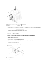
... fan. 5. 1 processor fan and heat sink assembly 2 clamp lever 3 bracket projection 4 clamp grip 5 bracket 4. Remove the computer cover (see System Board Components). 4. Inspiron™ 535/537 1 screws (2) 2 chassis fan Inspiron 545/546 Removing the Chassis Fan CAUTION: Do not touch the fan blades when you are removing the chassis fan. Slide the chassis...
... fan. 5. 1 processor fan and heat sink assembly 2 clamp lever 3 bracket projection 4 clamp grip 5 bracket 4. Remove the computer cover (see System Board Components). 4. Inspiron™ 535/537 1 screws (2) 2 chassis fan Inspiron 545/546 Removing the Chassis Fan CAUTION: Do not touch the fan blades when you are removing the chassis fan. Slide the chassis...
Service Manual
Page 24
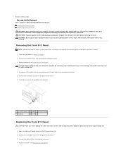
... the screw that shipped with any cover(s) (including computer covers, bezels, filler brackets, front-panel inserts, etc.) removed. Back to Contents Page Front I/O Panel Dell™ Inspiron™ 535/537/545/546 Service Manual Removing the Front I/O Panel Replacing the Front I /O panel out of all the cables that secures the I /O panel. 1. For additional...
... the screw that shipped with any cover(s) (including computer covers, bezels, filler brackets, front-panel inserts, etc.) removed. Back to Contents Page Front I/O Panel Dell™ Inspiron™ 535/537/545/546 Service Manual Removing the Front I/O Panel Replacing the Front I /O panel out of all the cables that secures the I /O panel. 1. For additional...
Service Manual
Page 26
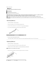
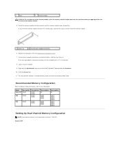
... Grasp the memory module and pull it from the electrical outlet before removing the cover. Press out the securing clip at www.dell.com/regulatory_compliance. Follow the memory installation guidelines (see Removing the Computer Cover). 3. WARNING: To guard against electrical shock, always ...the memory module is difficult to remove, gently ease the memory module back and forth to Contents Page Memory Dell™ Inspiron™ 535/537/545/546 Service Manual Removing Memory Replacing Memory Recommended Memory Configuration Setting Up Dual Channel Memory Configuration WARNING: Before...
... Grasp the memory module and pull it from the electrical outlet before removing the cover. Press out the securing clip at www.dell.com/regulatory_compliance. Follow the memory installation guidelines (see Removing the Computer Cover). 3. WARNING: To guard against electrical shock, always ...the memory module is difficult to remove, gently ease the memory module back and forth to Contents Page Memory Dell™ Inspiron™ 535/537/545/546 Service Manual Removing Memory Replacing Memory Recommended Memory Configuration Setting Up Dual Channel Memory Configuration WARNING: Before...
Service Manual
Page 27
...listed. To verify that memory size has changed, press to the table below: Model One module Two modules Three modules Four modules 535/537 DIMM1 DIMM1 NA NA DIMM2 545 DIMM1 DIMM1 DIMM3 DIMM1 DIMM3 DIMM2 DIMM1 DIMM3 DIMM2 DIMM4 546 DIMM1 DIMM1 DIMM2 DIMM1 DIMM2 DIMM3 DIMM1 ...insert the memory module correctly, the securing clips snap into position. If the message appears stating that the memory is not supported on Inspiron™ 535/537. Right-click the My Computer icon on to your Microsoft® Windows® desktop and click Properties. 10. If you apply equal...
...listed. To verify that memory size has changed, press to the table below: Model One module Two modules Three modules Four modules 535/537 DIMM1 DIMM1 NA NA DIMM2 545 DIMM1 DIMM1 DIMM3 DIMM1 DIMM3 DIMM2 DIMM1 DIMM3 DIMM2 DIMM4 546 DIMM1 DIMM1 DIMM2 DIMM1 DIMM2 DIMM3 DIMM1 ...insert the memory module correctly, the securing clips snap into position. If the message appears stating that the memory is not supported on Inspiron™ 535/537. Right-click the My Computer icon on to your Microsoft® Windows® desktop and click Properties. 10. If you apply equal...
Service Manual
Page 29
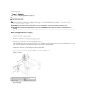
...these cables properly when you remove them from the system board and the drives. Back to Contents Page Power Supply Dell™ Inspiron™ 535/537/545/546 Service Manual Removing the Power Supply Replacing the Power Supply WARNING: Before working inside your computer, read ... 4. Remove all the cables from the securing clip on www.dell.com at the following location: www.dell.com/regulatory_compliance. Inspiron™ 535/537 1 power supply retention snap 2 screws (4) 3 power supply 4 voltage selector switch Inspiron 545/546 WARNING: To guard against electrical shock, always unplug ...
...these cables properly when you remove them from the system board and the drives. Back to Contents Page Power Supply Dell™ Inspiron™ 535/537/545/546 Service Manual Removing the Power Supply Replacing the Power Supply WARNING: Before working inside your computer, read ... 4. Remove all the cables from the securing clip on www.dell.com at the following location: www.dell.com/regulatory_compliance. Inspiron™ 535/537 1 power supply retention snap 2 screws (4) 3 power supply 4 voltage selector switch Inspiron 545/546 WARNING: To guard against electrical shock, always unplug ...
Service Manual
Page 31
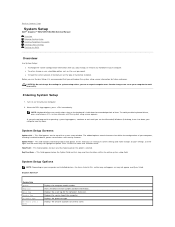
...® Windows® desktop, then shut down your computer. Displays the processor type. Back to Contents Page System Setup Dell™ Inspiron™ 535/537/545/546 Service Manual Overview Entering System Setup Clearing Forgotten Passwords Clearing CMOS Settings Flashing the BIOS Overview Use System Setup:... active. In this section may not appear, or may result when a key on the top of processor Level 2 cache. Inspiron 535/537 System Info System BIOS Info Asset Tag Service Tag Processor Type Processor Level 2 Cache Displays the computer model number. Displays the ...
...® Windows® desktop, then shut down your computer. Displays the processor type. Back to Contents Page System Setup Dell™ Inspiron™ 535/537/545/546 Service Manual Overview Entering System Setup Clearing Forgotten Passwords Clearing CMOS Settings Flashing the BIOS Overview Use System Setup:... active. In this section may not appear, or may result when a key on the top of processor Level 2 cache. Inspiron 535/537 System Info System BIOS Info Asset Tag Service Tag Processor Type Processor Level 2 Cache Displays the computer model number. Displays the ...
Service Manual
Page 32
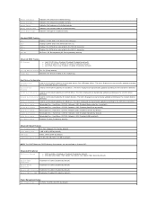
Halt On All Errors; Disabled (Enabled by default) Module Bay Identifies the device installed in Inspiron 537 Integrated Peripherals USB Device Setting l USB Controller-Enabled or Disabled (Enabled by default) Second Boot Device Removable Dev.; On (On by default) l Core Multi-Processing-...
Halt On All Errors; Disabled (Enabled by default) Module Bay Identifies the device installed in Inspiron 537 Integrated Peripherals USB Device Setting l USB Controller-Enabled or Disabled (Enabled by default) Second Boot Device Removable Dev.; On (On by default) l Core Multi-Processing-...
Setup Guide
Page 52
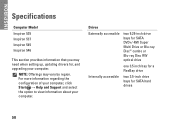
.... For more information regarding the configuration of your computer, click Start → Help and Support and select the option to view information about your computer. INSPIRON Specifications Computer Model Inspiron 535 Inspiron 537 Inspiron 545 Inspiron 546 This section provides information that you may vary by region.
.... For more information regarding the configuration of your computer, click Start → Help and Support and select the option to view information about your computer. INSPIRON Specifications Computer Model Inspiron 535 Inspiron 537 Inspiron 545 Inspiron 546 This section provides information that you may vary by region.


