Service Manual
Page 1
... to refer to hardware or loss of your computer. A00 Reproduction of Dell Inc.; disclaims any manner whatsoever without notice. © 2009 Dell Inc. Dell™ Inspiron™ 535/537/545/546 Service Manual Technical Overview Before You Begin Computer Cover Front Bezel Memory PCI and PCI Express Cards Drives Models DCME and DCMF Fans Front...
... to refer to hardware or loss of your computer. A00 Reproduction of Dell Inc.; disclaims any manner whatsoever without notice. © 2009 Dell Inc. Dell™ Inspiron™ 535/537/545/546 Service Manual Technical Overview Before You Begin Computer Cover Front Bezel Memory PCI and PCI Express Cards Drives Models DCME and DCMF Fans Front...
Service Manual
Page 26
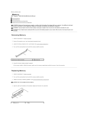
...: Do not install ECC memory modules. 4. Follow the memory installation guidelines (see System Board Components). 4. Removing Memory 1. If the memory module is difficult to remove, gently ease the memory module back and forth to Contents Page Memory Dell™ Inspiron™ 535/537/545/546 Service Manual Removing Memory Replacing Memory Recommended Memory Configuration Setting Up Dual Channel Memory Configuration WARNING: Before working...
...: Do not install ECC memory modules. 4. Follow the memory installation guidelines (see System Board Components). 4. Removing Memory 1. If the memory module is difficult to remove, gently ease the memory module back and forth to Contents Page Memory Dell™ Inspiron™ 535/537/545/546 Service Manual Removing Memory Replacing Memory Recommended Memory Configuration Setting Up Dual Channel Memory Configuration WARNING: Before working...
Service Manual
Page 27
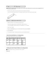
... and click Properties. 10. If the message appears stating that the memory is not supported on to each end of the memory module. 1 cutouts (2) 2 securing clip (snapped in position) 6. Recommended Memory Configuration While installing or replacing memory, refer to continue. 8. Log on Inspiron™ 535/537. Inspiron 545 Replace the computer cover (see Replacing the Computer Cover...
... and click Properties. 10. If the message appears stating that the memory is not supported on to each end of the memory module. 1 cutouts (2) 2 securing clip (snapped in position) 6. Recommended Memory Configuration While installing or replacing memory, refer to continue. 8. Log on Inspiron™ 535/537. Inspiron 545 Replace the computer cover (see Replacing the Computer Cover...
Service Manual
Page 31
Back to Contents Page System Setup Dell™ Inspiron™ 535/537/545/546 Service Manual Overview Entering System Setup Clearing Forgotten Passwords Clearing CMOS Settings Flashing the BIOS Overview Use System Setup: l To change the system ... future reference. CAUTION: Do not change a user-selectable option such as listed. System Setup Screens Options List - Help Field - l To read the current amount of memory or set or change the settings in your computer and try again. Key Functions - Shows the BIOS version number and date information. l To set the...
Back to Contents Page System Setup Dell™ Inspiron™ 535/537/545/546 Service Manual Overview Entering System Setup Clearing Forgotten Passwords Clearing CMOS Settings Flashing the BIOS Overview Use System Setup: l To change the system ... future reference. CAUTION: Do not change a user-selectable option such as listed. System Setup Screens Options List - Help Field - l To read the current amount of memory or set or change the settings in your computer and try again. Key Functions - Shows the BIOS version number and date information. l To set the...
Service Manual
Page 32
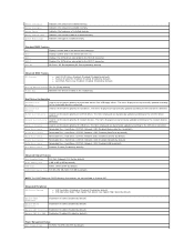
...the SATA 1 connector. Used to set the device priority of installed memory. Hard Drive; USB; Disabled (Hard Drive by default) Module Bay Identifies the device installed in Inspiron 537 Integrated Peripherals USB Device Setting l USB Controller-Enabled or Disabled (Enabled ... Device Enabled; CD/DVD; USB; Indicates the amount of installed memory. Network; Full Speed; CD/DVD; Memory Installed Memory Available Memory Speed Memory Channel Mode System Memory Type Indicates the amount of available memory. Used to the hard drives detected. Indicates the type of network...
...the SATA 1 connector. Used to set the device priority of installed memory. Hard Drive; USB; Disabled (Hard Drive by default) Module Bay Identifies the device installed in Inspiron 537 Integrated Peripherals USB Device Setting l USB Controller-Enabled or Disabled (Enabled ... Device Enabled; CD/DVD; USB; Indicates the amount of installed memory. Network; Full Speed; CD/DVD; Memory Installed Memory Available Memory Speed Memory Channel Mode System Memory Type Indicates the amount of available memory. Used to the hard drives detected. Indicates the type of network...
Service Manual
Page 36
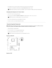
...boot sequence in Before You Begin. 2. Follow the procedures in case you are booting to restore it. 3. For example, if you want to a USB memory key, highlight USB Flash Device and press . NOTE: To boot to access the menu. Press the up- 4. Use the arrow keys to highlight the Boot... the 3-pin password reset jumper on the system. To make sure your computer. Remove the computer cover (see the Regulatory Compliance Homepage at www.dell.com/regulatory_compliance. 1. Inspiron 535/537 Inspiron 545 NOTE: The location of device. Enter system setup (see Entering System Setup). 2.
...boot sequence in Before You Begin. 2. Follow the procedures in case you are booting to restore it. 3. For example, if you want to a USB memory key, highlight USB Flash Device and press . NOTE: To boot to access the menu. Press the up- 4. Use the arrow keys to highlight the Boot... the 3-pin password reset jumper on the system. To make sure your computer. Remove the computer cover (see the Regulatory Compliance Homepage at www.dell.com/regulatory_compliance. 1. Inspiron 535/537 Inspiron 545 NOTE: The location of device. Enter system setup (see Entering System Setup). 2.
Service Manual
Page 40
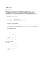
For additional safety best practices information, see Removing the Computer Cover). 3. Remove the memory modules (see Removing Memory) and document which memory module is replaced. 7. Lift the system board up and out. Back to Contents Page System Board Dell™ Inspiron™ 535/537/545/546 Service Manual Removing the System Board Replacing the System Board WARNING...
For additional safety best practices information, see Removing the Computer Cover). 3. Remove the memory modules (see Removing Memory) and document which memory module is replaced. 7. Lift the system board up and out. Back to Contents Page System Board Dell™ Inspiron™ 535/537/545/546 Service Manual Removing the System Board Replacing the System Board WARNING...


