
Owner's Manual
Page 145
...the Processor 1 Follow the procedures in the Product Information Guide. CAUTION: Despite having a plastic shield, the heat sink assembly may exist between the processor and heat sink. NOTICE: Strong thermal grease bond may be very hot during normal operation. Removing and Installing Parts 145 Processor... instructions located in "Before You Begin" on page 97. 2 Remove the computer cover (see "Removing the Computer Cover" on the opposite side. Do not use excessive force to separate the heat sink assembly from the processor to release the clamp grip from the bracket projection. 5 Release...
...the Processor 1 Follow the procedures in the Product Information Guide. CAUTION: Despite having a plastic shield, the heat sink assembly may exist between the processor and heat sink. NOTICE: Strong thermal grease bond may be very hot during normal operation. Removing and Installing Parts 145 Processor... instructions located in "Before You Begin" on page 97. 2 Remove the computer cover (see "Removing the Computer Cover" on the opposite side. Do not use excessive force to separate the heat sink assembly from the processor to release the clamp grip from the bracket projection. 5 Release...

Owner's Manual
Page 146
1 2 7 3 4 6 5 1 fan 4 bracket 7 clamp lever 2 fan cover 5 clamp grip 3 heat sink 6 bracket projection NOTICE: Unless a new heat sink is required for the new processor, reuse the original heat sink assembly when you replace the processor. 7 Pull the release lever straight up until the processor is released. 146 Removing and Installing Parts
1 2 7 3 4 6 5 1 fan 4 bracket 7 clamp lever 2 fan cover 5 clamp grip 3 heat sink 6 bracket projection NOTICE: Unless a new heat sink is required for the new processor, reuse the original heat sink assembly when you replace the processor. 7 Pull the release lever straight up until the processor is released. 146 Removing and Installing Parts

Owner's Manual
Page 150
7 6 1 5 2 4 3 1 clamp lever 4 bracket 7 fan 2 bracket projection 5 heat sink 3 clamp grip 6 fan cover 10 Connect any cables disconnected before removing the heat sink assembly. 11 Replace the computer cover (see "Replacing the Computer Cover" on page 164). 12 Connect your computer and devices to an electrical outlet, and turn them on. 13 Verify that the computer works correctly by running the Dell Diagnostics (see "Dell Diagnostics" on page 80). 150 Removing and Installing Parts
7 6 1 5 2 4 3 1 clamp lever 4 bracket 7 fan 2 bracket projection 5 heat sink 3 clamp grip 6 fan cover 10 Connect any cables disconnected before removing the heat sink assembly. 11 Replace the computer cover (see "Replacing the Computer Cover" on page 164). 12 Connect your computer and devices to an electrical outlet, and turn them on. 13 Verify that the computer works correctly by running the Dell Diagnostics (see "Dell Diagnostics" on page 80). 150 Removing and Installing Parts

Owner's Manual
Page 151
...electrical outlet before you begin any of the computer, be very hot during normal operation. Carelessness may be extremely careful. CAUTION: The heat sink assembly, power supply, and other unexpected injuries, always unplug your computer's electronic components. Removing the I/O Panel NOTE: Note the ... of the procedures in this section, follow the safety instructions in "Before You Begin" on page 97. 2 Remove the computer cover (see "Removing the Computer Cover" on page 99). 3 Remove the bezel (see "Removing the Bezel" on the computer chassis. I/O Panel CAUTION: Before you...
...electrical outlet before you begin any of the computer, be very hot during normal operation. Carelessness may be extremely careful. CAUTION: The heat sink assembly, power supply, and other unexpected injuries, always unplug your computer's electronic components. Removing the I/O Panel NOTE: Note the ... of the procedures in this section, follow the safety instructions in "Before You Begin" on page 97. 2 Remove the computer cover (see "Removing the Computer Cover" on page 99). 3 Remove the bezel (see "Removing the Bezel" on the computer chassis. I/O Panel CAUTION: Before you...

Owner's Manual
Page 154
...in contact with the processor. 154 Removing and Installing Parts CAUTION: The heat sink assembly, power supply, and other unexpected injuries, always unplug your computer from the electrical outlet before opening the cover. NOTICE: To prevent static damage to components inside your computer, discharge ...static electricity from the heat sink surface previously in "Before You Begin" on page 97. 2 Remove the computer cover (see "Removing the Computer Cover" on the top of the processor fan assembly. 7 Clean the grease from...
...in contact with the processor. 154 Removing and Installing Parts CAUTION: The heat sink assembly, power supply, and other unexpected injuries, always unplug your computer from the electrical outlet before opening the cover. NOTICE: To prevent static damage to components inside your computer, discharge ...static electricity from the heat sink surface previously in "Before You Begin" on page 97. 2 Remove the computer cover (see "Removing the Computer Cover" on the top of the processor fan assembly. 7 Clean the grease from...

Owner's Manual
Page 155
Removing and Installing Parts 155 1 2 3 1 fan 2 fan cover 3 heat sink 8 Hold the heat sink firmly in one hand and using moderate force, pull up the fan cover to separate it from the heat sink.
Removing and Installing Parts 155 1 2 3 1 fan 2 fan cover 3 heat sink 8 Hold the heat sink firmly in one hand and using moderate force, pull up the fan cover to separate it from the heat sink.

Owner's Manual
Page 158
3 Align and press the heat sink and fan assembly till both snap in place. 1 2 3 1 fan 2 fan cover 3 heat sink 4 Replace the heat sink assembly (see step 9 of "Installing the Processor" on page 148). 5 Replace the cables that were removed from the routing clips on top of the processor fan assembly. 158 Removing and Installing Parts
3 Align and press the heat sink and fan assembly till both snap in place. 1 2 3 1 fan 2 fan cover 3 heat sink 4 Replace the heat sink assembly (see step 9 of "Installing the Processor" on page 148). 5 Replace the cables that were removed from the routing clips on top of the processor fan assembly. 158 Removing and Installing Parts

Owner's Manual
Page 159
CAUTION: The heat sink assembly, power supply, and other unexpected injuries, always unplug your computer from your body before... may be very hot during normal operation. 6 Connect the processor fan cable to the system board (see "Replacing the Computer Cover" on page 164). 8 Connect your computer and devices to an electrical outlet, and turn them . CAUTION: To guard against... on the computer chassis. NOTICE: To prevent static damage to cool before opening the cover. Chassis Fan CAUTION: Before you touch them on. Be sure that the fan is correctly seated and secure. 7 Replace ...
CAUTION: The heat sink assembly, power supply, and other unexpected injuries, always unplug your computer from your body before... may be very hot during normal operation. 6 Connect the processor fan cable to the system board (see "Replacing the Computer Cover" on page 164). 8 Connect your computer and devices to an electrical outlet, and turn them . CAUTION: To guard against... on the computer chassis. NOTICE: To prevent static damage to cool before opening the cover. Chassis Fan CAUTION: Before you touch them on. Be sure that the fan is correctly seated and secure. 7 Replace ...

Owner's Manual
Page 162
...You Begin" on page 97. 2 Remove the computer cover (see "Removing Memory" on page 99). 3 Remove any add-in the same location after installing the new system board. 7 Remove the eight screws from the system board. CAUTION: The heat sink assembly, power supply, and other unexpected injuries, always unplug...in cards on the system board (see "Cards" on page 111). 4 Remove the processor and heat sink assembly (see "Processor" on page 145). 5 Remove the memory modules (see "Removing the Computer Cover" on page 111) and document which memory module is removed from each memory socket so that ...
...You Begin" on page 97. 2 Remove the computer cover (see "Removing Memory" on page 99). 3 Remove any add-in the same location after installing the new system board. 7 Remove the eight screws from the system board. CAUTION: The heat sink assembly, power supply, and other unexpected injuries, always unplug...in cards on the system board (see "Cards" on page 111). 4 Remove the processor and heat sink assembly (see "Processor" on page 145). 5 Remove the memory modules (see "Removing the Computer Cover" on page 111) and document which memory module is removed from each memory socket so that ...
Owner's Manual
Page 164
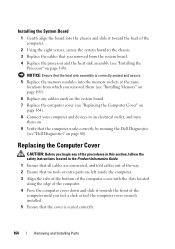
...fold cables out of the computer until you feel a click or feel the computer cover securely installed. 5 Ensure that the cover is seated correctly. 164 Removing and Installing Parts NOTICE: Ensure that the heat sink assembly is correctly seated and secure. 5 Replace the memory modules into the chassis...locations from the system board. 4 Replace the processor and the heat sink assembly (see "Dell Diagnostics" on page 148). Installing the System Board 1 Gently align the board into the memory sockets at the bottom of the computer cover with the slots located along the edge of the computer. ...
...fold cables out of the computer until you feel a click or feel the computer cover securely installed. 5 Ensure that the cover is seated correctly. 164 Removing and Installing Parts NOTICE: Ensure that the heat sink assembly is correctly seated and secure. 5 Replace the memory modules into the chassis...locations from the system board. 4 Replace the processor and the heat sink assembly (see "Dell Diagnostics" on page 148). Installing the System Board 1 Gently align the board into the memory sockets at the bottom of the computer cover with the slots located along the edge of the computer. ...


