
Setup and Specifications
Page 10
... PCI Express cards. 4 Power-supply diagnostics button Press to check the power‑supply state. 5 Power-supply diagnostics light Indicates the power-supply state. 6 Power port Connect a power cable to provide power to your computer. 7 ...Padlock ring(s) Attach a standard padlock to prevent unauthorized access to the interior of your computer. 2 Service Tag label The Service Tag is a unique alphanumeric identifier that enables Dell service technicians to identify the hardware components in enabled device. Provides video and audio output. 10 Views of Inspiron 3670...
... PCI Express cards. 4 Power-supply diagnostics button Press to check the power‑supply state. 5 Power-supply diagnostics light Indicates the power-supply state. 6 Power port Connect a power cable to provide power to your computer. 7 ...Padlock ring(s) Attach a standard padlock to prevent unauthorized access to the interior of your computer. 2 Service Tag label The Service Tag is a unique alphanumeric identifier that enables Dell service technicians to identify the hardware components in enabled device. Provides video and audio output. 10 Views of Inspiron 3670...
Service Manual
Page 4
... optical drive...31 Prerequisites...31 Procedure...31 19 Replacing the optical drive...33 Procedure...33 Post-requisites...34 20 Removing the power-supply unit...35 Prerequisites...35 Procedure...35 21 Replacing the power-supply unit...36 Procedure...36 Post-requisites...36 22 Removing the processor fan and heat-sink assembly 37 Prerequisites...37 Procedure...
... optical drive...31 Prerequisites...31 Procedure...31 19 Replacing the optical drive...33 Procedure...33 Post-requisites...34 20 Removing the power-supply unit...35 Prerequisites...35 Procedure...35 21 Replacing the power-supply unit...36 Procedure...36 Post-requisites...36 22 Removing the processor fan and heat-sink assembly 37 Prerequisites...37 Procedure...
Service Manual
Page 8
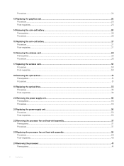
... #6-32x6.35 Quantity 2 Screw image Solid-state drive/Intel System board M2x3.5 1 Optane memory Card-retention bracket Chassis #6-32x6.35 1 Wireless card System board M2x3.5 1 Power-supply unit Chassis #6-32x6.35 4 3.5-inch hard drive Chassis 2.5-inch hard drive(s) NOTE: Depending on the configuration ordered there may require the following tools: • Phillips...
... #6-32x6.35 Quantity 2 Screw image Solid-state drive/Intel System board M2x3.5 1 Optane memory Card-retention bracket Chassis #6-32x6.35 1 Wireless card System board M2x3.5 1 Power-supply unit Chassis #6-32x6.35 4 3.5-inch hard drive Chassis 2.5-inch hard drive(s) NOTE: Depending on the configuration ordered there may require the following tools: • Phillips...
Service Manual
Page 10
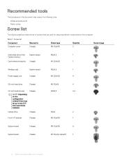
... 1 processor fan and heat-sink assembly 3 graphics card 5 wireless card 7 2.5-inch hard drive 9 memory module(s) 11 2.5-inch hard drive 2 solid-state drive/Intel Optane memory 4 power-supply unit 6 3.5-inch hard drive 8 system board 10 coin-cell battery 12 optical-disk drive 10 Technical overview Topics: • Inside view of your computer •... inside your computer, follow the steps in After working inside your computer. For more safety best practices, see the Regulatory Compliance home page at www.dell.com/ regulatory_compliance.
... 1 processor fan and heat-sink assembly 3 graphics card 5 wireless card 7 2.5-inch hard drive 9 memory module(s) 11 2.5-inch hard drive 2 solid-state drive/Intel Optane memory 4 power-supply unit 6 3.5-inch hard drive 8 system board 10 coin-cell battery 12 optical-disk drive 10 Technical overview Topics: • Inside view of your computer •... inside your computer, follow the steps in After working inside your computer. For more safety best practices, see the Regulatory Compliance home page at www.dell.com/ regulatory_compliance.
Service Manual
Page 11
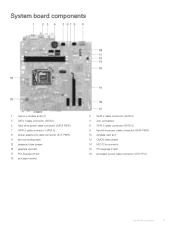
System board components 1 memory-module slots (2) 3 SATA 1 cable connector (SATA 1) 5 hard-drive power cable connector (SATA PWR) 7 SATA 0 cable connector (SATA 0) 9 power-supply unit cable connector (ATX PWR) 11 service mode jumper 13 password clear jumper 15 graphics card slot 17... PCI-Express X1 slot 19 processor socket 2 SATA 2 cable connector (SATA 2) 4 coin-cell battery 6 SATA 3 cable connector (SATA 3) 8 hard-drive power cable connector (SATA PWR)...
System board components 1 memory-module slots (2) 3 SATA 1 cable connector (SATA 1) 5 hard-drive power cable connector (SATA PWR) 7 SATA 0 cable connector (SATA 0) 9 power-supply unit cable connector (ATX PWR) 11 service mode jumper 13 password clear jumper 15 graphics card slot 17... PCI-Express X1 slot 19 processor socket 2 SATA 2 cable connector (SATA 2) 4 coin-cell battery 6 SATA 3 cable connector (SATA 3) 8 hard-drive power cable connector (SATA PWR)...
Service Manual
Page 35
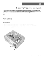
... the Regulatory Compliance home page at www.dell.com/ regulatory_compliance. 20 Removing the power-supply unit WARNING: Before working inside your computer, read the safety information that secure the power-supply unit to the chassis. 5 Lift the power-supply unit along with your computer and follow the... 1 Press the securing clip and disconnect the power-supply unit cable (P1) from the system board (ATX SYS). 2 Press the securing clip and disconnect the power-supply unit cable (P2) from the processor-power cable (ATX CPU). 3 Remove the power-supply unit cable (P1) from the routing guide ...
... the Regulatory Compliance home page at www.dell.com/ regulatory_compliance. 20 Removing the power-supply unit WARNING: Before working inside your computer, read the safety information that secure the power-supply unit to the chassis. 5 Lift the power-supply unit along with your computer and follow the... 1 Press the securing clip and disconnect the power-supply unit cable (P1) from the system board (ATX SYS). 2 Press the securing clip and disconnect the power-supply unit cable (P2) from the processor-power cable (ATX CPU). 3 Remove the power-supply unit cable (P1) from the routing guide ...

Service Manual
Page 36
... the chassis. 4 Connect the power-supply unit cable (P1) to the system board (ATX SYS). 5 Connect the power-supply unit cable (P2) to the processor-power cable (ATX CPU). For more safety best practices, see the Regulatory Compliance home page at www.dell.com/ regulatory_compliance. Topics: •...; Procedure • Post-requisites Procedure 1 Place the power-supply unit on the chassis, aligning the screw holes on the power-supply unit to the screw holes on the chassis. 2 Replace ...
... the chassis. 4 Connect the power-supply unit cable (P1) to the system board (ATX SYS). 5 Connect the power-supply unit cable (P2) to the processor-power cable (ATX CPU). For more safety best practices, see the Regulatory Compliance home page at www.dell.com/ regulatory_compliance. Topics: •...; Procedure • Post-requisites Procedure 1 Place the power-supply unit on the chassis, aligning the screw holes on the power-supply unit to the screw holes on the chassis. 2 Replace ...
Service Manual
Page 51
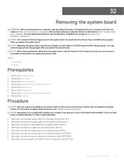
...fan and heat-sink assembly. 8 Remove the processor. NOTE: Depending on system board connectors, see the Regulatory Compliance home page at www.dell.com/ regulatory_compliance. NOTE: Replacing the system board removes any changes you have up to the BIOS using the BIOS setup program. Procedure ...drive data cable from the system board (SATA 3). 6 Disconnect the hard-drive power cable from the system board (SATA PWR). 7 Disconnect the hard-drive power cables from the system board (SATA PWR). 8 Disconnect the power-supply unit cable (P1) from the system board, note the location of all cables...
...fan and heat-sink assembly. 8 Remove the processor. NOTE: Depending on system board connectors, see the Regulatory Compliance home page at www.dell.com/ regulatory_compliance. NOTE: Replacing the system board removes any changes you have up to the BIOS using the BIOS setup program. Procedure ...drive data cable from the system board (SATA 3). 6 Disconnect the hard-drive power cable from the system board (SATA PWR). 7 Disconnect the hard-drive power cables from the system board (SATA PWR). 8 Disconnect the power-supply unit cable (P1) from the system board, note the location of all cables...

Service Manual
Page 57
7 Connect the power-supply unit cable (P1) to the system board (ATX CPU). 8 Connect the hard-drive power cables to the system board (SATA PWR). 9 Connect the hard-drive power cable to the system board (SATA PWR). 10 Connect the hard-drive data cable to the system board (SATA 3). 11 Connect the hard-drive cable to the system board (SATA 0). 12 Connect the hard-drive data cable to the system board (SATA 1). 13 Connect the optical-drive data cable to the system board (SATA 2). 14 Connect the processor-power cable to the system board (ATX SYS). Replacing the system board 57
7 Connect the power-supply unit cable (P1) to the system board (ATX CPU). 8 Connect the hard-drive power cables to the system board (SATA PWR). 9 Connect the hard-drive power cable to the system board (SATA PWR). 10 Connect the hard-drive data cable to the system board (SATA 3). 11 Connect the hard-drive cable to the system board (SATA 0). 12 Connect the hard-drive data cable to the system board (SATA 1). 13 Connect the optical-drive data cable to the system board (SATA 2). 14 Connect the processor-power cable to the system board (ATX SYS). Replacing the system board 57


