
Me and My For Inspiron XPS and Alienware computers
Page 4
Memory module...20 System board...20 Chipset...20 Processor...20 Computer fan...21 Heat sink...21 Thermal grease...21 Video card...21 TV tuners...22 Speakers......
Memory module...20 System board...20 Chipset...20 Processor...20 Computer fan...21 Heat sink...21 Thermal grease...21 Video card...21 TV tuners...22 Speakers......
Me and My For Inspiron XPS and Alienware computers
Page 18
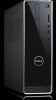
...computer without turning off . Some of the common types of drives are also physically similar to read -only, write-once, or re-writeable. Memory cards Memory cards, also referred to as digital cameras, mobile phones, media players, gaming consoles, and so on . Your computer may support a DVD... are installed on your computer The most common internal storage devices are commonly used removable storage devices include: • Optical discs • Memory cards • Flash drives • External hard drives Optical drives and discs Your computer may have a media-card reader to HDDs, ...
...computer without turning off . Some of the common types of drives are also physically similar to read -only, write-once, or re-writeable. Memory cards Memory cards, also referred to as digital cameras, mobile phones, media players, gaming consoles, and so on . Your computer may support a DVD... are installed on your computer The most common internal storage devices are commonly used removable storage devices include: • Optical discs • Memory cards • Flash drives • External hard drives Optical drives and discs Your computer may have a media-card reader to HDDs, ...

Me and My For Inspiron XPS and Alienware computers
Page 20
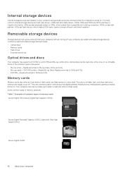
... various controllers and connectors that your computer Generally, the chipset is part of the computer. Memory Stick (MS)/Memory Stick Pro (MS Pro) Smart Media/Smart Media XD Memory module A memory module stores temporary data that help in laptop computers. Faster and higher amount of computers. ...the chipset may also have integrated graphics, sound, and network capabilities. System board A system board forms the central part of memory generally provides better performance. However, with each other devices connect to the system board to be integrated in MHz). Any file...
... various controllers and connectors that your computer Generally, the chipset is part of the computer. Memory Stick (MS)/Memory Stick Pro (MS Pro) Smart Media/Smart Media XD Memory module A memory module stores temporary data that help in laptop computers. Faster and higher amount of computers. ...the chipset may also have integrated graphics, sound, and network capabilities. System board A system board forms the central part of memory generally provides better performance. However, with each other devices connect to the system board to be integrated in MHz). Any file...

Me and My For Inspiron XPS and Alienware computers
Page 21
... a fan mounted above or beside them from overheating, malfunctioning, and damage. Keeping the components cool helps in GigaHertz (GHz) or MegaHertz (MHz) • On-board memory, also referred to as cache These aspects also determine the performance of metal. Processors are used to dissipate heat generated by expelling hot air from...
... a fan mounted above or beside them from overheating, malfunctioning, and damage. Keeping the components cool helps in GigaHertz (GHz) or MegaHertz (MHz) • On-board memory, also referred to as cache These aspects also determine the performance of metal. Processors are used to dissipate heat generated by expelling hot air from...

Me and My For Inspiron XPS and Alienware computers
Page 22
...the processor and provides higher data transfer rates while reducing the power consumption. • Discrete- In some video cards also have dedicated memory on the cardsand generally provide higher performance than integrated videocards. These cards are best suited for desktop and laptop computers as ; 2, ...;definition video games, and so on using TV tuners, see the documentation for audio output. Integrated video cards generally share the system memory (RAM) and the may support 3.5 mm audio connector, USB, or wireless connection to perform video processing. NOTE: When a discrete...
...the processor and provides higher data transfer rates while reducing the power consumption. • Discrete- In some video cards also have dedicated memory on the cardsand generally provide higher performance than integrated videocards. These cards are best suited for desktop and laptop computers as ; 2, ...;definition video games, and so on using TV tuners, see the documentation for audio output. Integrated video cards generally share the system memory (RAM) and the may support 3.5 mm audio connector, USB, or wireless connection to perform video processing. NOTE: When a discrete...

Me and My For Inspiron XPS and Alienware computers
Page 49
..., otherwise press to finish the test. Do you want to run the remaining memory tests? NOTE: Press Esc anytime during the test to abort testing and restart your computer. 2. To contact Dell for technical support, see the Windows desktop, then restart your screen: No problems have been found with ...can use the Pre-Boot System Assessment (PSA) to diagnose various hardware problems. The ePSA tests devices such as the system board, keyboard, display, memory, hard drive, and so on. This will take about 30 seconds, plug in diagnostic tools to help you determine the issue with your computer. ...
..., otherwise press to finish the test. Do you want to run the remaining memory tests? NOTE: Press Esc anytime during the test to abort testing and restart your computer. 2. To contact Dell for technical support, see the Windows desktop, then restart your screen: No problems have been found with ...can use the Pre-Boot System Assessment (PSA) to diagnose various hardware problems. The ePSA tests devices such as the system board, keyboard, display, memory, hard drive, and so on. This will take about 30 seconds, plug in diagnostic tools to help you determine the issue with your computer. ...

Me and My For Inspiron XPS and Alienware computers
Page 50
...that can be tested using ePSA. • Results- The Stat column displays the status of the tests. • Status bar appears at the Dell logo to them. Select Diagnostics and press Enter. 4. NOTE: Peripherals may have been found with your peripheral. Starting LCD BIST 1. Restart the ...can be supported on -screen instructions to wait until you wait too long and the operating system logo appears, continue to run the remaining memory tests? NOTE: If you see the Windows desktop, then restart your computer. 2. Turn on . Follow the instructions on the screen ...
...that can be tested using ePSA. • Results- The Stat column displays the status of the tests. • Status bar appears at the Dell logo to them. Select Diagnostics and press Enter. 4. NOTE: Peripherals may have been found with your peripheral. Starting LCD BIST 1. Restart the ...can be supported on -screen instructions to wait until you wait too long and the operating system logo appears, continue to run the remaining memory tests? NOTE: If you see the Windows desktop, then restart your computer. 2. Turn on . Follow the instructions on the screen ...

Me and My For Inspiron XPS and Alienware computers
Page 51
...detected NOTE: If you are errors or problems. This series of the beep codes mentioned in the Status window displays the errors that the memory module is supported for assistance. Three Four Five Six Seven Possible system board failure-Chipset error RAM read/write failure Real‑time Clock failure... problems Beep codes Possible problems One Possible system board failure-BIOS ROM checksum failure. If this occurs, note the beep code and contact Dell for computers with errors, the following message appears on your computer. Press to continue if you installed or replaced the...
...detected NOTE: If you are errors or problems. This series of the beep codes mentioned in the Status window displays the errors that the memory module is supported for assistance. Three Four Five Six Seven Possible system board failure-Chipset error RAM read/write failure Real‑time Clock failure... problems Beep codes Possible problems One Possible system board failure-BIOS ROM checksum failure. If this occurs, note the beep code and contact Dell for computers with errors, the following message appears on your computer. Press to continue if you installed or replaced the...

Me and My For Inspiron XPS and Alienware computers
Page 52
...system configuration information after you add, change, or remove any BIOS settings, you press F2 before working inside your computer. During POST, when the DELL logo is initialized. This prompt can use a coin‑cell battery that the keyboard is displayed, watch for it , see the desktop. To... reset the password, remove the coin‑cell battery, wait for the F2 prompt to change settings such as amount of memory, type of hard drive, and so on (or restart) your computer and try again. Use system‑board jumper NOTE: System-board jumper ...
...system configuration information after you add, change, or remove any BIOS settings, you press F2 before working inside your computer. During POST, when the DELL logo is initialized. This prompt can use a coin‑cell battery that the keyboard is displayed, watch for it , see the desktop. To... reset the password, remove the coin‑cell battery, wait for the F2 prompt to change settings such as amount of memory, type of hard drive, and so on (or restart) your computer and try again. Use system‑board jumper NOTE: System-board jumper ...

Me and My For Inspiron XPS and Alienware computers
Page 55
... resume full-power operation (typically within a few seconds) when you want to start working again. • Hibernation-Hibernation puts your open documents and programs in memory and on your computer storage, and then puts your computer into a low-power state so that you can choose a plan from the list of yourcomputer...
... resume full-power operation (typically within a few seconds) when you want to start working again. • Hibernation-Hibernation puts your open documents and programs in memory and on your computer storage, and then puts your computer into a low-power state so that you can choose a plan from the list of yourcomputer...

Service Manual
Page 4
... optical drive...32 Prerequisites...32 Procedure...32 17 Replacing the optical drive...35 Procedure...35 Post-requisites...36 18 Removing the memory modules 37 Prerequisites...37 Procedure...37 19 Replacing the memory modules 38 Procedure...38 Post-requisites...38 20 Removing the coin-cell battery 39 Prerequisites...39 Procedure...39 21 Replacing...
... optical drive...32 Prerequisites...32 Procedure...32 17 Replacing the optical drive...35 Procedure...35 Post-requisites...36 18 Removing the memory modules 37 Prerequisites...37 Procedure...37 19 Replacing the memory modules 38 Procedure...38 Post-requisites...38 20 Removing the coin-cell battery 39 Prerequisites...39 Procedure...39 21 Replacing...

Service Manual
Page 8
... LED is strapped to any bare metal on the system being worked on office desks or cubicles. An example of memory integrity, intermittent memory errors, etc. The use wireless wrist straps. ESD field service kit The unmonitored Field Service kit is not immediately ... approved methods of damage to recognize and troubleshoot is recommended to damage over time. ESDsensitive items are typically installed in previous Dell products. It is the intermittent (also called latent or "walking wounded") failure. Intermittent failures represent approximately 80 percent of...
... LED is strapped to any bare metal on the system being worked on office desks or cubicles. An example of memory integrity, intermittent memory errors, etc. The use wireless wrist straps. ESD field service kit The unmonitored Field Service kit is not immediately ... approved methods of damage to recognize and troubleshoot is recommended to damage over time. ESDsensitive items are typically installed in previous Dell products. It is the intermittent (also called latent or "walking wounded") failure. Intermittent failures represent approximately 80 percent of...

Service Manual
Page 13
drive cage 2. power-supply unit Inside view of your computer Figure 1. memory modules 3. system board 4. 4 Inside view of your computer 13 hard-drive assembly 6. processor fan and heat-sink assembly 5. Inside view of your computer 1.
drive cage 2. power-supply unit Inside view of your computer Figure 1. memory modules 3. system board 4. 4 Inside view of your computer 13 hard-drive assembly 6. processor fan and heat-sink assembly 5. Inside view of your computer 1.

Service Manual
Page 37
...up. 2. Follow the procedure from step 1 to remove it Removing the memory modules 37 NOTE: If the memory module is difficult to remove, gently ease the memory module back and forth alongside the memory-module slot to step 6 in After working inside your computer. Remove ...the computer cover. 2. Procedure 1. Using the fingertips, spread apart the securing clip at www.dell.com/regulatory_compliance. Prerequisites 1. 18 Removing the memory modules NOTE: Before working inside your computer, read the safety information that shipped with your computer and follow ...
...up. 2. Follow the procedure from step 1 to remove it Removing the memory modules 37 NOTE: If the memory module is difficult to remove, gently ease the memory module back and forth alongside the memory-module slot to step 6 in After working inside your computer. Remove ...the computer cover. 2. Procedure 1. Using the fingertips, spread apart the securing clip at www.dell.com/regulatory_compliance. Prerequisites 1. 18 Removing the memory modules NOTE: Before working inside your computer, read the safety information that shipped with your computer and follow ...

Service Manual
Page 38
... safety best practices, see the Regulatory Compliance home page at www.dell.com/regulatory_compliance. Insert the memory module into the memory-module slot and press the memory module down until the securing clips lock in Before working inside your computer. 19 Replacing the memory modules NOTE: Before working inside your computer, read the safety information...
... safety best practices, see the Regulatory Compliance home page at www.dell.com/regulatory_compliance. Insert the memory module into the memory-module slot and press the memory module down until the securing clips lock in Before working inside your computer. 19 Replacing the memory modules NOTE: Before working inside your computer, read the safety information...

Service Manual
Page 59
...the processor socket. After working inside your computer, follow the steps in Before working inside your computer. Remove the memory modules. 5. Remove the thermal-cooling assembly. Removing the processor 59 For more safety best practices, see the Regulatory Compliance home page at... www.dell.com/regulatory_compliance. Remove the fan shroud. 6. 34 Removing the processor NOTE: Before working inside your computer, read the safety ...
...the processor socket. After working inside your computer, follow the steps in Before working inside your computer. Remove the memory modules. 5. Remove the thermal-cooling assembly. Removing the processor 59 For more safety best practices, see the Regulatory Compliance home page at... www.dell.com/regulatory_compliance. Remove the fan shroud. 6. 34 Removing the processor NOTE: Before working inside your computer, read the safety ...

Service Manual
Page 60
... in the package. When the processor is fully seated in the kit to ensure that thermal conductivity is achieved. Replace the memory modules. 4. 35 Replacing the processor NOTE: Before working inside your computer, read the safety information that shipped with the tabs... computer. Replace the thermal-cooling assembly. 2. Replace the front bezel. 6. CAUTION: The pin-1 corner of the processor are aligned at www.dell.com/regulatory_compliance. Replace the fan shroud. 3. NOTE: A new processor ships with a thermal pad in After working inside your computer, follow the...
... in the package. When the processor is fully seated in the kit to ensure that thermal conductivity is achieved. Replace the memory modules. 4. 35 Replacing the processor NOTE: Before working inside your computer, read the safety information that shipped with the tabs... computer. Replace the thermal-cooling assembly. 2. Replace the front bezel. 6. CAUTION: The pin-1 corner of the processor are aligned at www.dell.com/regulatory_compliance. Replace the fan shroud. 3. NOTE: A new processor ships with a thermal pad in After working inside your computer, follow the...

Service Manual
Page 61
... board. Follow the procedure from the chassis. For information on system board connectors, see the Regulatory Compliance home page at www.dell.com/regulatory_compliance. 36 Removing the system board NOTE: Before working inside your computer, read the safety information that shipped with your... system board, note the location of all cables as you remove them correctly after you replace the system board. Prerequisites 1. Remove the memory modules. 5. Remove the wireless card. 6. NOTE: Your computer's Service Tag is stored in Before working inside your computer, follow the...
... board. Follow the procedure from the chassis. For information on system board connectors, see the Regulatory Compliance home page at www.dell.com/regulatory_compliance. 36 Removing the system board NOTE: Before working inside your computer, read the safety information that shipped with your... system board, note the location of all cables as you remove them correctly after you replace the system board. Prerequisites 1. Remove the memory modules. 5. Remove the wireless card. 6. NOTE: Your computer's Service Tag is stored in Before working inside your computer, follow the...

Service Manual
Page 65
Align and place the front-I /O bracket to step 8 in "Replacing the optical drive". 6. Replace the screw (#6-32x6.35) that secure the front-I /O bracket on the chassis. 10. Post-requisites 1. Replace the processor. 2. Replace the wireless card. 4. Follow the procedure from step 5 to the chassis. Replace the front bezel. Replacing the system board 65 Replace the thermal-cooling assembly. 3. 9. Replace the memory modules. 5.
Align and place the front-I /O bracket to step 8 in "Replacing the optical drive". 6. Replace the screw (#6-32x6.35) that secure the front-I /O bracket on the chassis. 10. Post-requisites 1. Replace the processor. 2. Replace the wireless card. 4. Follow the procedure from step 5 to the chassis. Replace the front bezel. Replacing the system board 65 Replace the thermal-cooling assembly. 3. 9. Replace the memory modules. 5.

Service Manual
Page 68
...Current Clock Speed Displays the current processor clock speed. Table 3. Asset Tag Displays the Asset Tag of Slot2. Memory Speed Displays the memory speed. Processor L2 Cache Displays the processor L2 Cache size. Ownership Tag Displays the Ownership Tag of the computer... setup System setup options-General menu General System Information BIOS version Displays the BIOS version number. DIMM 2 Size Displays the DIMM 2 memory size. Maximum Clock Speed Displays the maximum processor clock speed. • SATA Hard Drive (if available) • Diagnostics NOTE:...
...Current Clock Speed Displays the current processor clock speed. Table 3. Asset Tag Displays the Asset Tag of Slot2. Memory Speed Displays the memory speed. Processor L2 Cache Displays the processor L2 Cache size. Ownership Tag Displays the Ownership Tag of the computer... setup System setup options-General menu General System Information BIOS version Displays the BIOS version number. DIMM 2 Size Displays the DIMM 2 memory size. Maximum Clock Speed Displays the maximum processor clock speed. • SATA Hard Drive (if available) • Diagnostics NOTE:...


